Mint roll package

a technology of rolling package and rolling pin, applied in the field of rolling package, can solve the problems of complex packing design, complex or time-consuming, and no longer treat packaging, and achieve the effect of reducing the width of the control slo

Active Publication Date: 2005-10-11
INTERCONTINENTAL GREAT BRANDS LLC
View PDF8 Cites 30 Cited by
  • Summary
  • Abstract
  • Description
  • Claims
  • Application Information

AI Technical Summary

Benefits of technology

[0005]In accordance with the present invention a package assembly for the storage and distribution of a plurality of stacked mints is provided. The package assembly includes a cylindrical outer shell including a shell sidewall, a shell bottom surface, and a shell open top. The shell sidewall includes a sidewall inner surface and a sidewall outer surface. A vertical control slot is formed in the shell sidewall, the vertical control slot having a control slot height and a control slot width. At least one retention protrusion is formed onto a slot side edge such that the control slot width is reduced in the location of the at least one retention protrusion. A cylindrical inner insert including an insert sidewall, an insert top surface, and an insert open bottom, is formed to house the plurality of stacked mints. The cylindrical inner insert is positioned within the cylindrical outer shell such that the insert open bottom faces the shell bottom surface. A control pad is formed onto and protrudes outwards from the insert sidewall. The control pad is positioned within the vertical control slot and is movable such that the cylindrical inner insert can be moved between a closed position and an open position. The control pad has a control pad width such that said control pad engages the at least one retention protrusion when in the closed position and such that the cylindrical inner insert is resisted from moving into the open position. A dispensing chamber is formed in the insert sidewall adjoining the insert top surface. The dispensing chamber is covered by the shell sidewall when the cylindrical inner insert is in the closed position. The dispensing chamber is positioned outside the cylindrical outer shell when the cylindrical inner insert is in the open position. The dispensing chamber has a dispensing chamber height sufficient to allow one of the plurality of stacked mints to be removed from the cylindrical inner insert.

Problems solved by technology

Packaging can no longer be treated as simply a utilitarian element utilized to bring a product to market.
Unique designs and dispensing features, in the case of mints or candy, can often result in complex packing designs.
This may result in complex or time consuming manufacturing that may negatively impact the cost associated with a product's distribution.
If these costs are passed on to the consumer, they may in turn negatively impact the perception of the product or its value.

Method used


Image

  • Mint roll package
  • Mint roll package
  • Mint roll package

Examples


Embodiment Construction

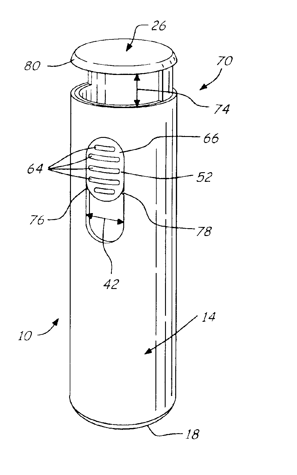
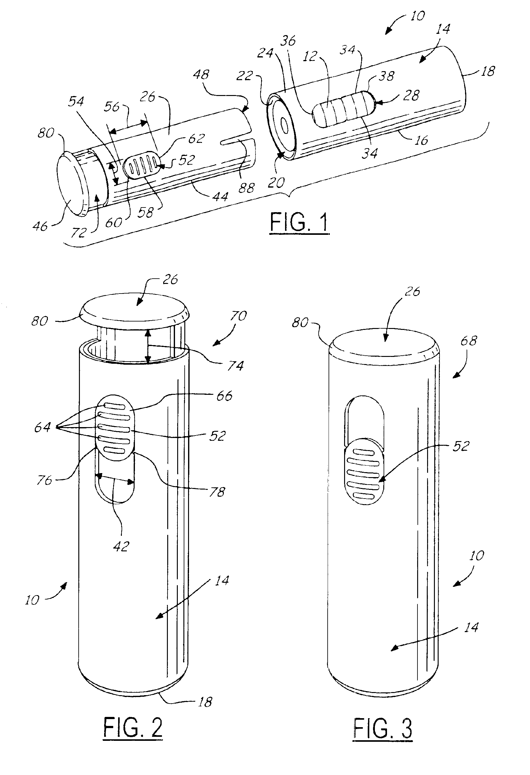
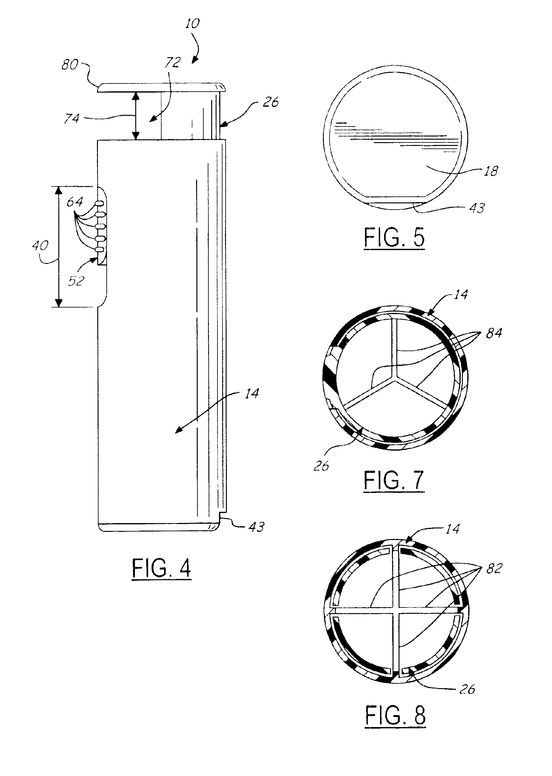
[0015]Referring now to FIG. 1, which is an illustration of a package assembly 10 for the storage and distribution of a plurality of stacked mints 12 in accordance with the present invention. The package assembly 10 is intended for the storage and distribution of stacked mints 12 or other similar candies. It is contemplated, however, that the present invention may be utilized for the storage and distribution of a variety of products. The package assembly 10 includes a cylindrical outer shell 14 including a shell sidewall 16, a shell bottom surface 18, and a shell open top 20. The shell sidewall 16 includes a sidewall inner surface 22 and a sidewall outer surface 24. Although the cylindrical outer shell 14 can be formed in a variety of fashions, one embodiment contemplates an injection molded cylindrical outer shell 14.

[0016]The cylindrical outer shell 14 works in concert with a cylindrical inner insert 26 to provide a simple two-piece injected molded assembly 10 for the storage and d...


PUM


Abstract

A package assembly 10 for the storage and distribution of a plurality of stacked mints 12 is provided. The package assembly 10 includes a cylindrical outer shell 14 including a shell sidewall 16, a shell bottom surface 18, and a shell open top 20. The shell sidewall 16 includes a sidewall inner surface 22 and a sidewall outer surface 24. A vertical control slot 28 is formed in the shell sidewall 16, the vertical control slot 28 having a control slot height 40 and a control slot width 42. At least one retention protrusion 78 is formed onto a slot side edge 34 such that the control slot width 42 is reduced in the location of the at least one retention protrusion 78. A cylindrical inner insert 26 including an insert sidewall 44, an insert top surface 46, and an insert open bottom 48, is formed to house the plurality of stacked mints 12. The cylindrical inner insert 26 is positioned within the cylindrical outer shell 14 such that the insert open bottom 48 faces the shell bottom surface 18. A control pad 52 is formed onto and protrudes outwards from the insert sidewall 44. The control pad 52 is positioned within the vertical control slot 28 and is movable such that the cylindrical inner insert 26 can be moved between a closed position 68 and an open position 70. The control pad 52 has a control pad width 54 such that said control pad 52 engages the at least one retention protrusion 78 when in the closed position 68 and such that the cylindrical inner insert 26 is resisted from moving into the open position 70. A dispensing chamber 72 is formed in the insert sidewall 44 adjoining the insert top surface 46. The dispensing chamber 72 is covered by the shell sidewall 16 when the cylindrical inner insert 26 is in the closed position 68. The dispensing chamber 72 is positioned outside the cylindrical outer shell 14 when the cylindrical inner insert 26 is in the open position 70. The dispensing chamber 72 has a dispensing chamber height 74 sufficient to allow one of the plurality of stacked mints 12 to be removed from the cylindrical inner insert 26.

Description

TECHNICAL FIELD[0001]The present invention relates generally to a package for the storage and distribution of mints and similar candy and more specifically a package for the storage and distribution of mints with improved manufacturing and assembly characteristics.BACKGROUND OF THE INVENTION[0002]Packaging can no longer be treated as simply a utilitarian element utilized to bring a product to market. Appearance, ease of use, shape, configuration, and a variety of other packaging characteristics have been found to effect a customer's perception of the product contained within. Consumers may also attribute the perceived quality of the packaging with the product contained within. Additionally, the unique aspects of a packaging design and its unique functions can develop consumer identity that may further promote product sales.[0003]As a result of such considerations, packaging design has taken on an increased significance to product manufacturers. Unique designs and dispensing features...

Claims


Application Information

Patent Timeline
Patent Type & Authority Patents(United States)
IPC IPC(8): B65D83/04
CPCB65D83/0409B65D2583/0431
Inventor DEVINE, DANIEL
Owner INTERCONTINENTAL GREAT BRANDS LLC
Why Eureka
Try Eureka