Progressive power lens

a technology of progressive power and lens, applied in the field of progressive power lenses, can solve the problems of insufficient widening of the vision area, wearer's so-called swinging of images, uncomfortable feelings to wearers, etc., and achieve the effect of wide vision and sufficient reduction of transmission astigmatism of the lens

Inactive Publication Date: 2005-10-11
HOYA LENS THAILAND LTD +1
View PDF14 Cites 2 Cited by
  • Summary
  • Abstract
  • Description
  • Claims
  • Application Information

AI Technical Summary

Benefits of technology

[0030]The present invention is advantageous in that it provides a spectacle lens which is configured to have substantially wide vision while transmission astigmatism of the lens is reduced sufficiently.

Problems solved by technology

It is almost impossible to widen a clear vision area from the distance portion through the near portion.
With regard to the general-purpose progressive power lens, there is a problem that the wearer feels a so-called swinging of images due to distortion of an image which is caused by aberration in the middle portion and in particular in side areas within the middle portion when the wearer moves his / her line of sight relatively fast by shaking his / her head vertically or horizontally.
The swinging of images causes uncomfortable feelings to the wearer.
In this case, the balance between the right and left lenses is lost and therefore aesthetic appearance of the spectacles is damaged.
However, if the right and left lenses are designed considering only forms of the lenses so that base curves of the right and left lenses are matched with each other, aberration increases because in general a form of the lens which minimizes aberration with reference to required refractive power is limited.
Consequently, optical performance deteriorates.
However, a progressive power lens family having a uniform aberration balance for different base curves and for different spherical dioptric power has not been provided.

Method used


Image

  • Progressive power lens
  • Progressive power lens
  • Progressive power lens

Examples


first embodiment

[0082

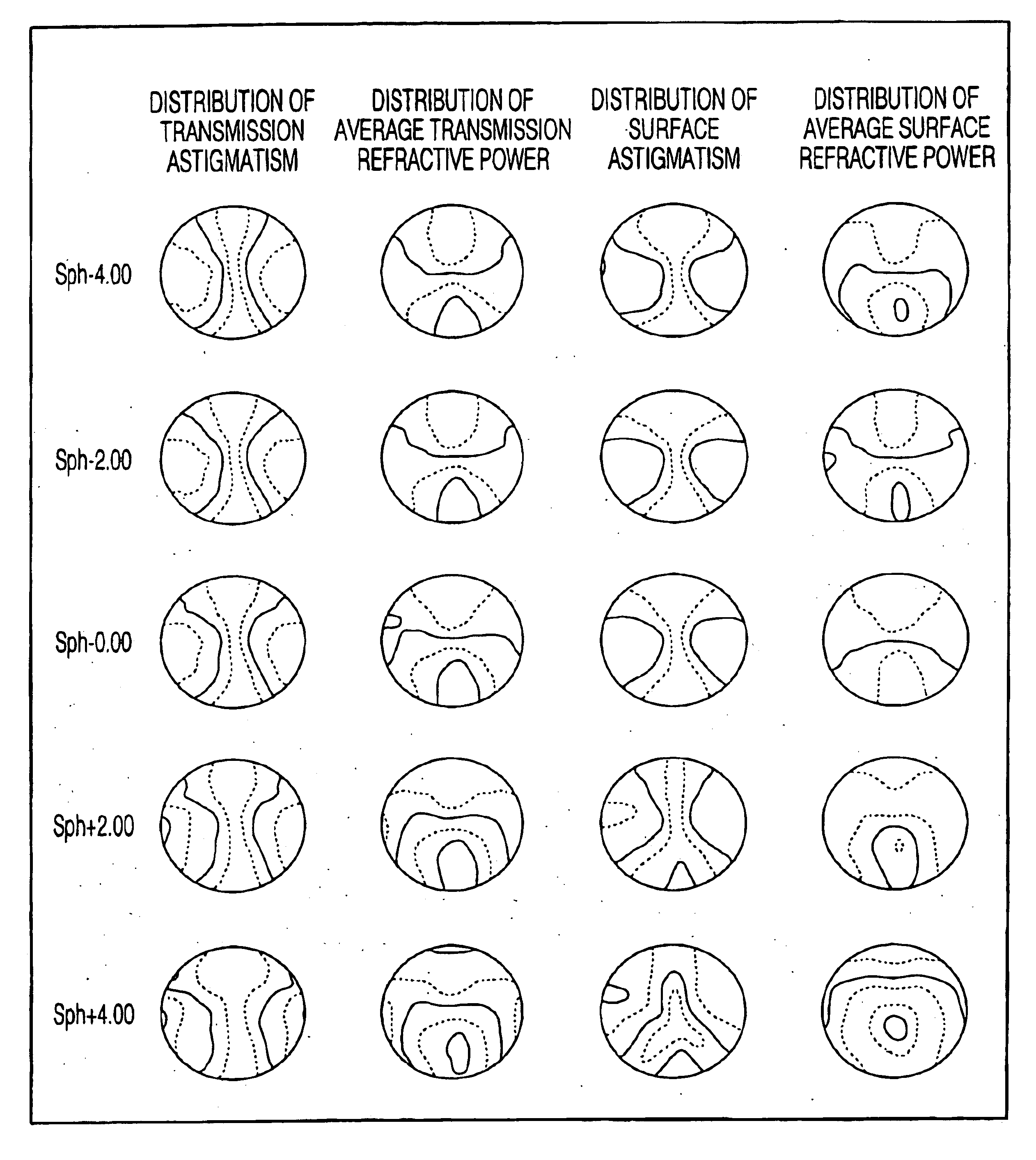
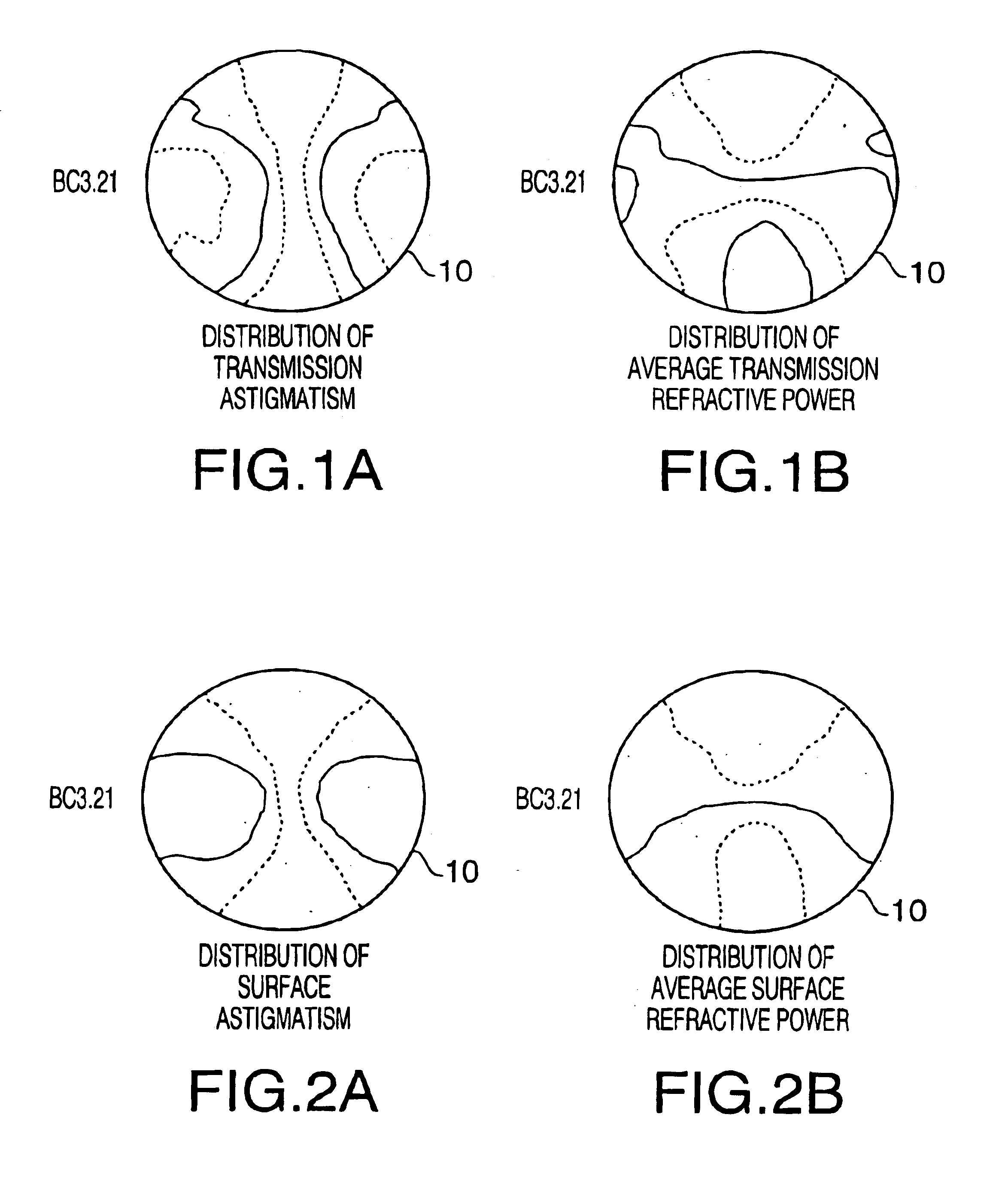
[0083]FIGS. 1A and 1B show transmission performance of a progressive power lens 10 according to a first embodiment of the invention. FIG. 1A shows distribution of transmission astigmatism of the progressive power lens 10. FIG. 1B shows distribution of average transmission refractive power of the progressive power lens 10. In each of FIGS. 1A and 1B (and in each of the following distribution maps), an interval between adjacent contour lines corresponds to 0.5 (unit: D). The progressive spectacle lens 10 has a diameter of 60 mm.

[0084]FIGS. 2A and 2B show surface performance of the progressive power lens 10. FIGS. 2A and 2B respectively show distribution of surface astigmatism and distribution of average surface refractive power of the progressive power lens 10.

[0085]The transmission performance shown in FIGS. 1A and 1B is a target optical performance of a series of progressive power lenses according to the first embodiment of the invention. The series of progressive power lenses ...

second embodiment

[0119

[0120]FIGS. 13A and 13B respectively show distribution of transmission astigmatism and distribution of average transmission refractive power of a progressive power lens 20 according to a second embodiment of the invention. In each of FIGS. 13A and 13B (and in each of the following distribution maps), an interval between adjacent contour lines corresponds to 0.5 (unit: D). The progressive power lens 20 has a diameter of 60 mm.

[0121]FIGS. 14A and 14B respectively show distribution of surface astigmatism and distribution of average surface refractive power of the progressive power lens 20.

[0122]The transmission performance shown in FIGS. 13A and 13B is a target optical performance of a series of progressive power lenses according to the second embodiment of the invention. The series of progressive power lenses is designed to attain the transmission performance shown in FIGS. 13A and 13B.

[0123]The progressive power lens 20, a so-called progressive power lens for short distance, has...


PUM


Abstract

A progressive power lens belonging to a series of lenses according to the present invention is provided. If a first lens and a second lens randomly chosen from the series of progressive power lenses have a common spherical refractive power Sph [diopter] in the distance portions thereof, the Sph is greater than or equal to +1, and a base curve BC1 of the first lens is smaller than a base curve BC2 of the second lens, the first and second lenses satisfy a condition: Wds⁡(BC1,Sph)Wns⁡(BC1,Sph)Wdt⁡(BC1,Sph)Wnt⁡(BC1,Sph)<Wds⁡(BC2,Sph)Wns⁡(BC2,Sph)Wdt⁡(BC2,Sph)Wnt⁡(BC2,Sph).(1)

Description

BACKGROUND OF THE INVENTION[0001]The present invention relates to a progressive power lens used for correction of presbyopia.[0002]The progressive power lenses for correction of presbyopia are developed and widely used. When the progressive power lens is designed and evaluated, the progressive power lens is often considered to have three portions: a distance portion for distance vision, a middle portion for middle vision and a near portion for near vision. Since refractive power within the middle portion changes continuously, the middle portion is referred to as a progressive area.[0003]In general, clear definitions concerning object distances for the above three portions are not given. Therefore, in this specification, the term “distance portion” means a portion of a lens (i.e., a portion in a field of view of the lens) for viewing objects at relatively long distances, the term “near portion” means a portion of the lens for viewing objects at relatively short distances, and the ter...

Claims


Application Information

Patent Timeline
Patent Type & Authority Patents(United States)
IPC IPC(8): G02C7/02G02C7/06
CPCG02C7/061G02C7/063G02C7/066G02C2202/08
Inventor SATO, HIROSHIYAMAMOTO, CHIKARASHIRAYANAGI, MORIYASU
Owner HOYA LENS THAILAND LTD
Why Eureka
Try Eureka