Vehicle pillar structure

a technology of pillars and vehicles, applied in the direction of superstructure connections, superstructure subunits, windows, etc., can solve the problems of narrowing the field of vision of drivers, and achieve the effects of improving collision performance, improving manufacturing efficiency, and improving collision performan

Active Publication Date: 2020-04-30
TOYOTA JIDOSHA KK
View PDF0 Cites 1 Cited by
  • Summary
  • Abstract
  • Description
  • Claims
  • Application Information

AI Technical Summary

Benefits of technology

[0022]In the seventh aspect, the molding member is attached to a location of the vehicle inner face of the transparent member that overlaps the second column, and the molding member is provided with the rear screening portion. The rear screening portion is spaced apart from and on the first column side of the superimposed welding location of the second column, and extends such that the leading end portion approaches or abuts the second column. Accordingly, the superimposed weld of the second column is covered from the first column side, namely the vehicle front side, by the rear screening portion. The superimposed welding location of the second column can accordingly be made less noticeable when the driver views a target object on the far side of the front pillar through the transparent member between the first column and the second column, and when the second column is viewed from outside the vehicle through the transparent member.
[0023]As explained above, the vehicle pillar structure according to the first aspect enables both a wide field of vision to be secured when driving the vehicle, and improved collision performance in a frontal collision.
[0024]The vehicle pillar structures according to the second and third aspects enable improved collision performance in a frontal collision.
[0025]The vehicle pillar structure according to the fourth aspect enables manufacturing efficiency to be improved.
[0026]The vehicle pillar structures according to the fifth to seventh aspects enable external styling properties to be improved.

Problems solved by technology

However, configuring retention members in tube shapes would increase the width of the front pillar itself, narrowing the field of vision of the driver.

Method used


Image

  • Vehicle pillar structure
  • Vehicle pillar structure
  • Vehicle pillar structure

Examples


Embodiment Construction

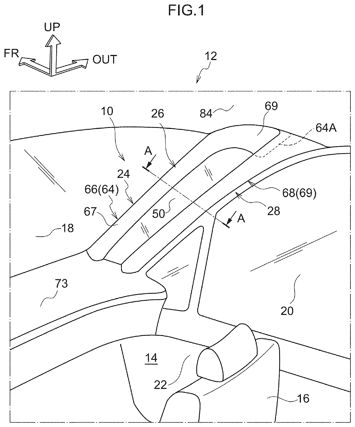
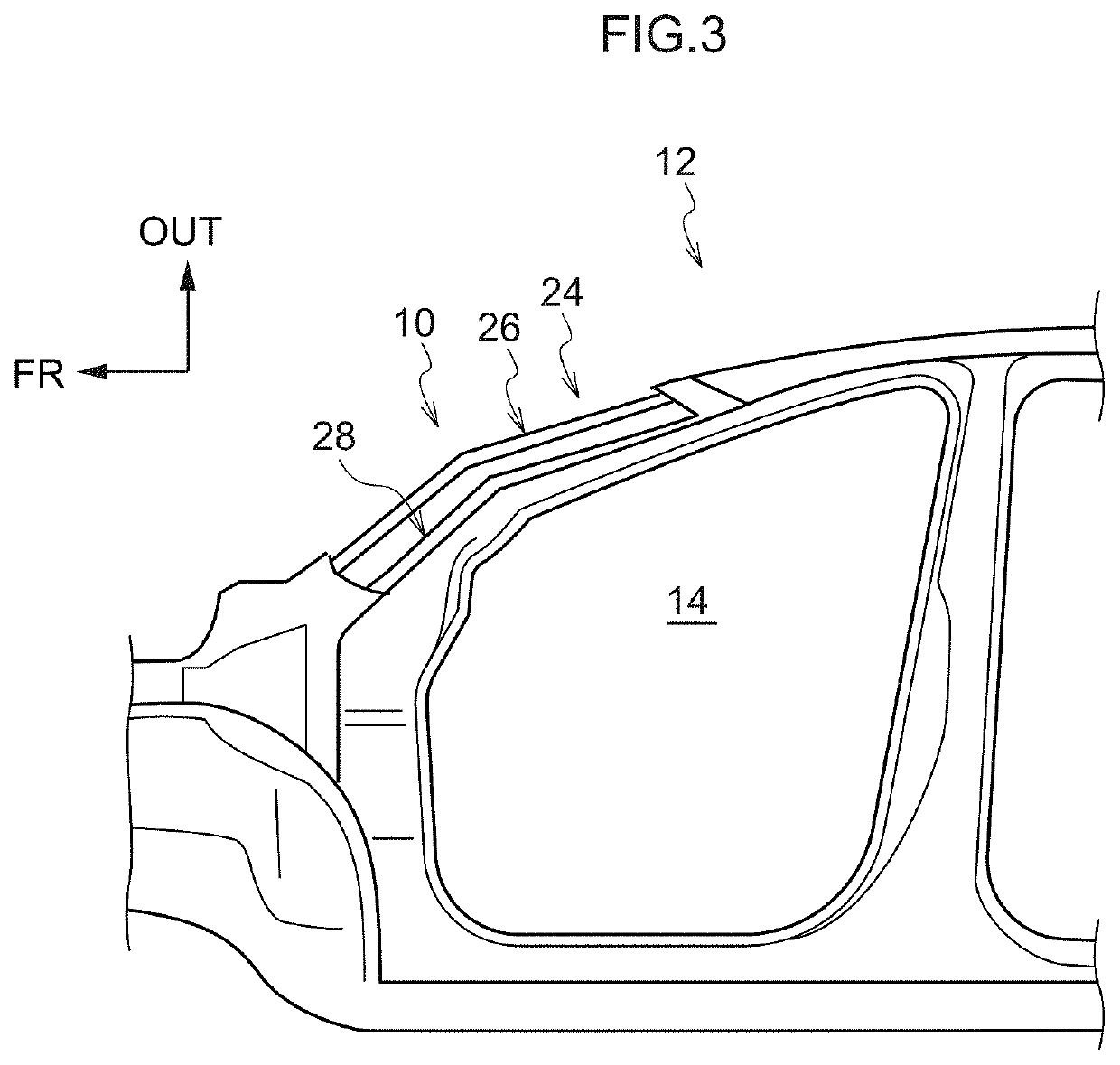
[0031]Explanation follows regarding an exemplary embodiment of a vehicle pillar structure according to the present disclosure, with reference to FIG. 1 to FIG. 3. In the drawings, the arrow FR indicates a vehicle front-rear direction front side, the arrow OUT indicates a vehicle width direction outer side, and the arrow UP indicates a vehicle vertical direction upper side.

[0032]Overall Configuration

[0033]As illustrated in FIG. 1, a pair of left and right vehicle seats 16 are installed at a vehicle front side inside a vehicle cabin 14 of a vehicle 12 applied with a vehicle pillar structure 10 according to the present exemplary embodiment. One of the vehicle seats 16 seats a driver, not illustrated in the drawings. As an example, the vehicle 12 of the present exemplary embodiment is a left-hand drive vehicle, and the vehicle seat 16 on the driving seat side is omitted from illustration in the drawings.

[0034]Front windshield glass (referred to hereafter simply as “front glass”) 18 is p...


PUM


Abstract

A vehicle pillar structure including a first column, a second column, and a transparent member. The first column includes a first framework member in a substantially plate shape extending along a vehicle vertical direction, and a second framework member in a substantially plate shape extending along the vehicle vertical direction and opposite the first framework member. The second column is at the vehicle rear side of the first column with a spacing between the first column and the second column, and includes a third framework member in a substantially plate shape extending along the vehicle vertical direction, and a fourth framework member in a substantially plate shape extending along the vehicle vertical direction, and opposite the third framework member. The transparent member spans between the first column and the second column, and enables outside of a vehicle to be seen when viewed from a driving seat side.

Description

CROSS-REFERENCE TO RELATED APPLICATION[0001]This application claims priority under 35 USC 119 from Japanese Patent Application No. 2018-202210, filed on Oct. 26, 2018, the disclosure of which is incorporated by reference herein in its entirety.BACKGROUNDTechnical Field[0002]The present disclosure relates to a vehicle pillar structure.Related Art[0003]Japanese Patent Application Laid-Open (JP-A) No. 2017-7509 discloses an invention relating to a vehicle pillar structure. In this vehicle pillar structure, a front pillar framework is configured from a hollow, substantially rectangular column shaped transparent member. Respective retention portions are provided at a vehicle width direction inner side and vehicle width direction outer side of the transparent member. This enables a driver to see a target object on the far side of the front pillar through the transparent member between the two retention portions.[0004]However, in the vehicle pillar structure disclosed in JP-A No. 2017-7509...

Claims


Application Information

Patent Timeline
Patent Type & Authority Applications(United States)
IPC IPC(8): B60J1/08B62D25/04B62D27/02
CPCB62D27/02B60J1/08B62D25/04
Inventor KAMIMURA, SHINYAMIYASHITA, TOSHIYAIKEDA, KOKI
Owner TOYOTA JIDOSHA KK
Why Eureka
Try Eureka