Impact separation type pedal

a technology of impact separation and pedal, which is applied in the direction of pedestrian/occupant safety arrangement, mechanical control devices, instruments, etc., can solve the problems of difficult backward rotation, insufficient rigidity of the stopper at the cowl crossbar, and inability to secure the safety of an oblique collision under, etc., to achieve simple structure, improve collision performance, and reduce manufacturing costs

Active Publication Date: 2018-09-25
HYUNDAI MOTOR CO LTD +1
View PDF13 Cites 1 Cited by
  • Summary
  • Abstract
  • Description
  • Claims
  • Application Information

AI Technical Summary

Benefits of technology

[0018]According to the impact separation type pedal for a vehicle of the present disclosure, the pedal is separated by a larger deformation of the dash panel than of a cowl fixing portion in a collision. The pedal can thus be separated even under various collision conditions particularly such as front / offset or small overlap collisions and oblique collisions. The disclosed pedal does not injure a driver and also provides the following effects.
[0019]First, reduction of the manufacturing cost is achieved because the pedal has a simple structure as compared with existing pedal stopper technology or backward rotation technology. Second, improvement of collision performance is achieved because the pedal hinge for separating the pedal is definitely separated even in any collision conditions. Third, improvement of strength is achieved because the pedal member rigidity-securing distance is decreased, as compared with the related art. Thus, the disclosed pedal is very advantageous in terms of strength and rigidity. Strength and rigidity are improved by adding a separation wall rib using a cross-coupling member applied to the hinge portion of the pedal. Fourth, improved operability of the pedal is achieved because a pedal stroke by spherical contact is made that provides smooth operation of the pedal by applying a ball to the structure for separating the pedal at the hinge portion in a collision. Fifth, improvement of the commercial value of the pedal is achieved because the disclosed pedal satisfies oblique collision regulations that are severe collision conditions.

Problems solved by technology

However, the anti-pedal pushing structure of the backward rotation type or the pedal stopper type secure only safety in an offset collision or a small overlap collision, but do not secure safety in an oblique collision under NHTSA.
When the pedal diagonally collides, the backward rotation lever cannot be rotated, so it is difficult to rotate backward.
The stopper at the cowl crossbar does not have enough rigidity to resist a pedal pushed in an oblique collision of a vehicle.
The pedal stopper has to have substantial strength, which necessarily increases the manufacturing cost and weight.
It is thus difficult to deal with this type of collision even with the most common pedal stopper.

Method used


Image

  • Impact separation type pedal
  • Impact separation type pedal
  • Impact separation type pedal

Examples


Embodiment Construction

[0031]Hereinafter, embodiments of the present disclosure are described in detail with reference to the accompanying drawings. The present disclosure may be achieved in various alternate ways by those having ordinary skill in the art, so the present disclosure is not limited to the disclosed embodiments.

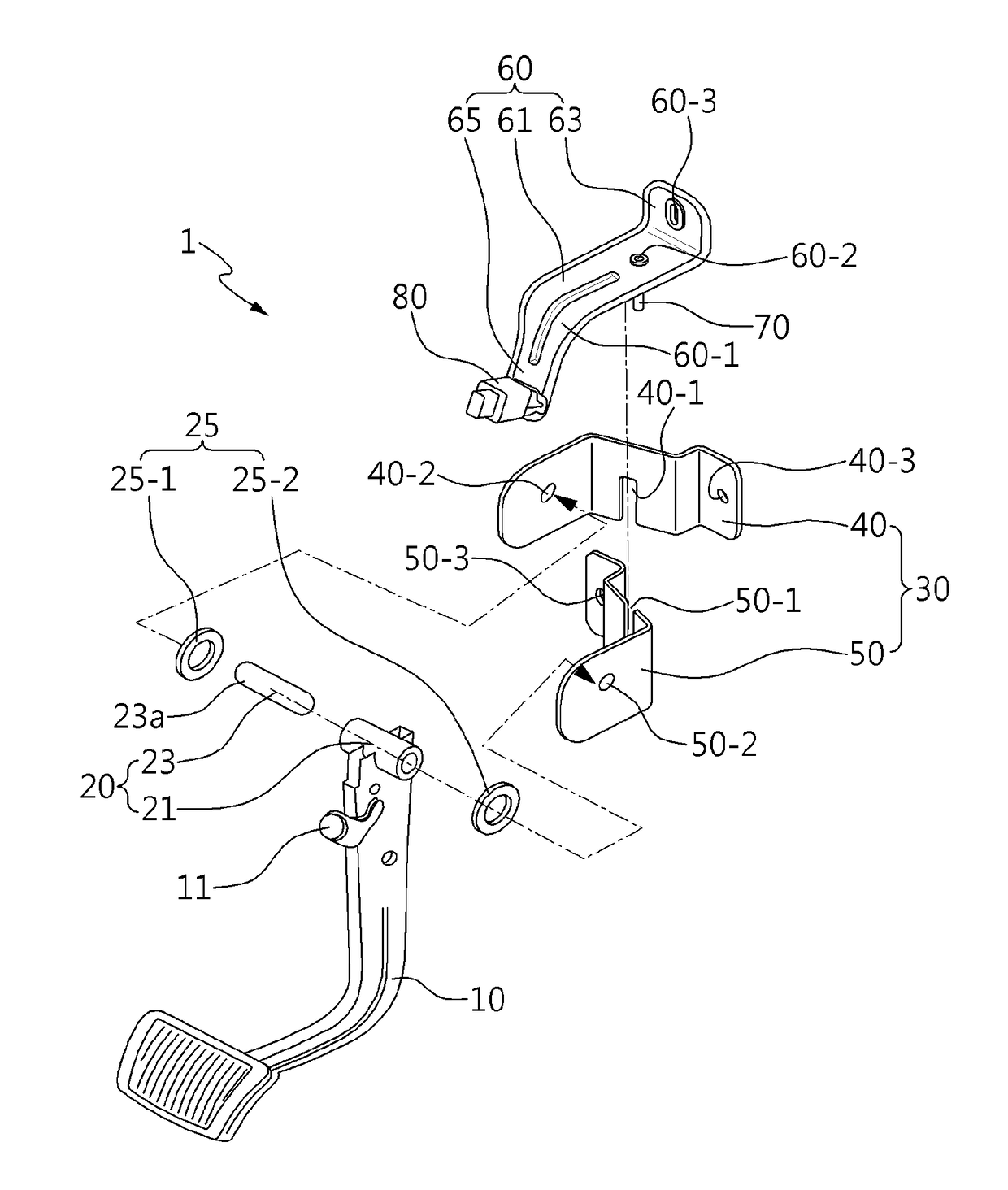
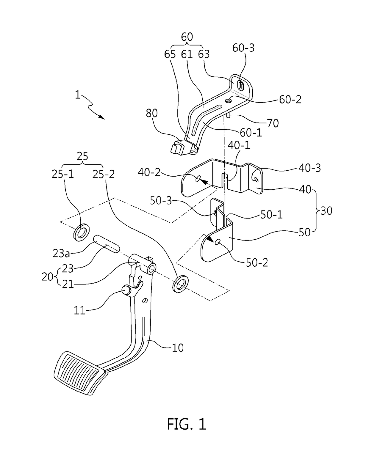
[0032]Referring to FIG. 1, a pedal 1 includes a pedal arm 10, a hinge 20, a pedal separator 30, a cover bracket 60, and a fixing pin 70. Further, the pedal 1 may include a kick-down switch 80.

[0033]The pedal arm 10 has a footing, i.e., a foot plate and pad at the lower portion and makes a pedal stroke about the hinge 20, which is coupled to the upper portion above the footing.

[0034]The hinge 20 is disposed through the upper portion above the footing of the pedal arm 10 and functions as a rotational center when the pedal arm 10 is pressed down by a driver. To this end, the hinge 20 is composed of a hinge pipe 21, a hinge pin 23, and a hinge bushing 25. For example, the hinge pipe 21, w...


PUM


Abstract

The present disclosure provides a pedal 1 that includes a left bracket and right bracket that are combined such that a portion coupled to a hinge of a pedal arm and another portion fixed to a vehicle body are fitted to each other in an X-shape. A cover bracket is welded to the left and right brackets and over the X-shaped portion. A fixing pin welded to the left and right brackets and at a cross-point of the X-shape. The pedal arm is separated due to deformation in an impact direction in an oblique collision as well as a front, offset, or small overlap collision of a vehicle. Thus, the pedal makes it possible to prevent a driver from being injured by the pedal.

Description

CROSS-REFERENCE TO RELATED APPLICATIONS[0001]This application claims priority to and the benefit of Korean Patent Application No. 10-2017-0081794, filed on Jun. 28, 2017, which is incorporated herein by reference in its entirety.BACKGROUNDField of the Disclosure[0002]The present disclosure relates to an impact separation type pedal and, more particularly, to an impact separation type pedal that satisfies an oblique test.Description of Related Art[0003]In general, a pedal anti-pushing structure is applied to the pedals in vehicles to prevent a driver from being injured by the pedals that are pushed toward the driver in a vehicle collision. In this disclosure, pedals mean a brake pedal, a clutch pedal, and an accelerator pedal.[0004]For example, the pedal anti-pushing structure is rotated backward in a backward rotation type pedal when being pushed backward or prevents the pedals from being pushed in a pedal stopper type pedal when a vehicle is in an offset collision or a small overla...

Claims


Application Information

Patent Timeline
Patent Type & Authority Patents(United States)
IPC IPC(8): G05G1/30G05G1/327B60T7/06B60K26/02G05G1/44B60K23/02
CPCG05G1/327B60T7/065B60K26/02G05G1/44B60K23/02B60Y2400/402B60R21/09B60R2021/0009
Inventor KIM, EUN-SIK
Owner HYUNDAI MOTOR CO LTD
Why Eureka
Try Eureka