Indicator lamp comprising an optical device for recovering and distributing the light flux towards an annular reflector

Inactive Publication Date: 2005-10-11
VALEO VISION SA
View PDF28 Cites 86 Cited by
  • Summary
  • Abstract
  • Description
  • Claims
  • Application Information

AI Technical Summary

Benefits of technology

[0013]The indicator lamp according to the invention must allow the use of a light source that is substantially punctiform, such as a light-e

Problems solved by technology

The indicator lamps obtained from this combination have the drawback th

Method used


Image

  • Indicator lamp comprising an optical device for recovering and distributing the light flux towards an annular reflector
  • Indicator lamp comprising an optical device for recovering and distributing the light flux towards an annular reflector
  • Indicator lamp comprising an optical device for recovering and distributing the light flux towards an annular reflector

Examples


first embodiment

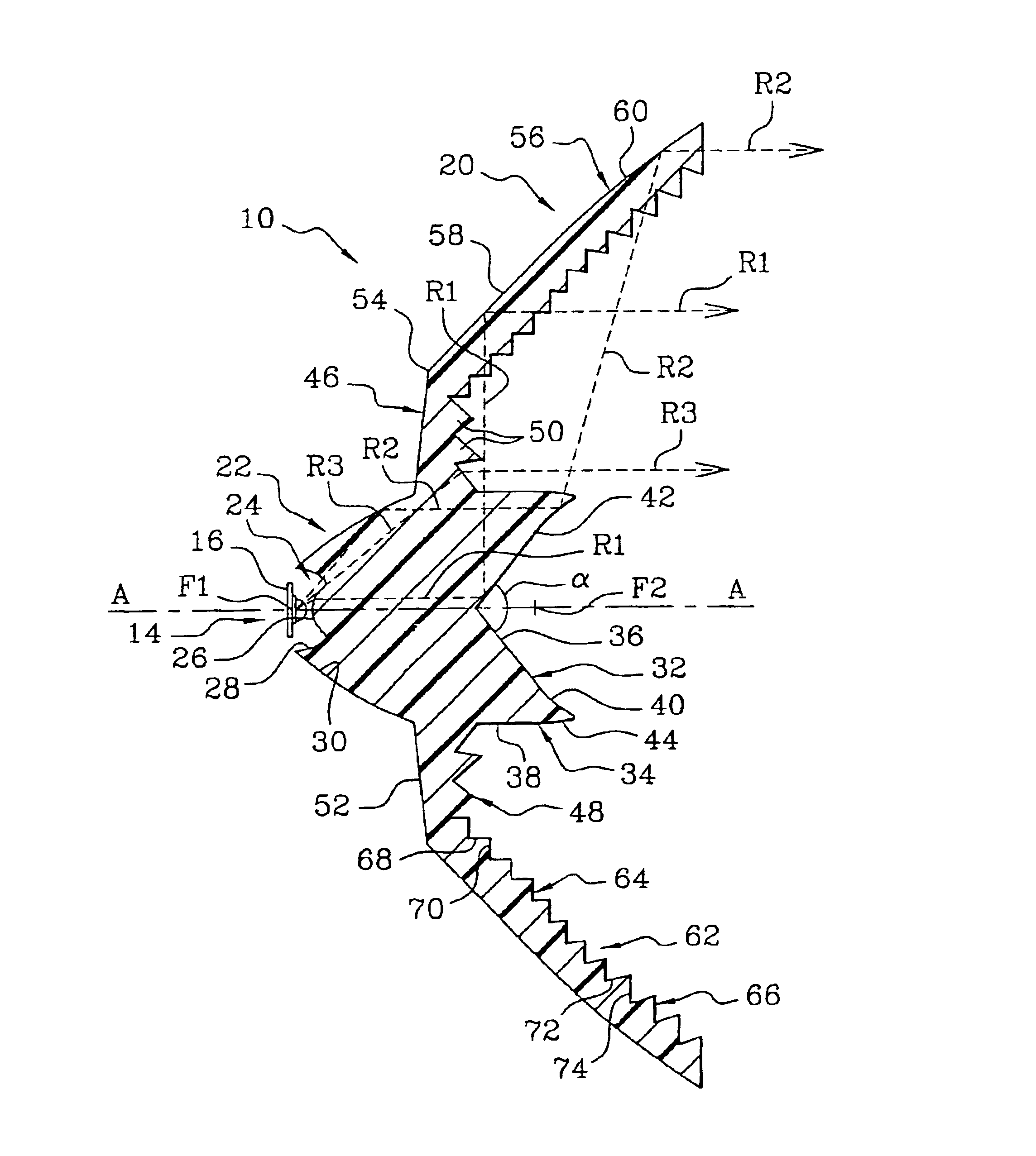
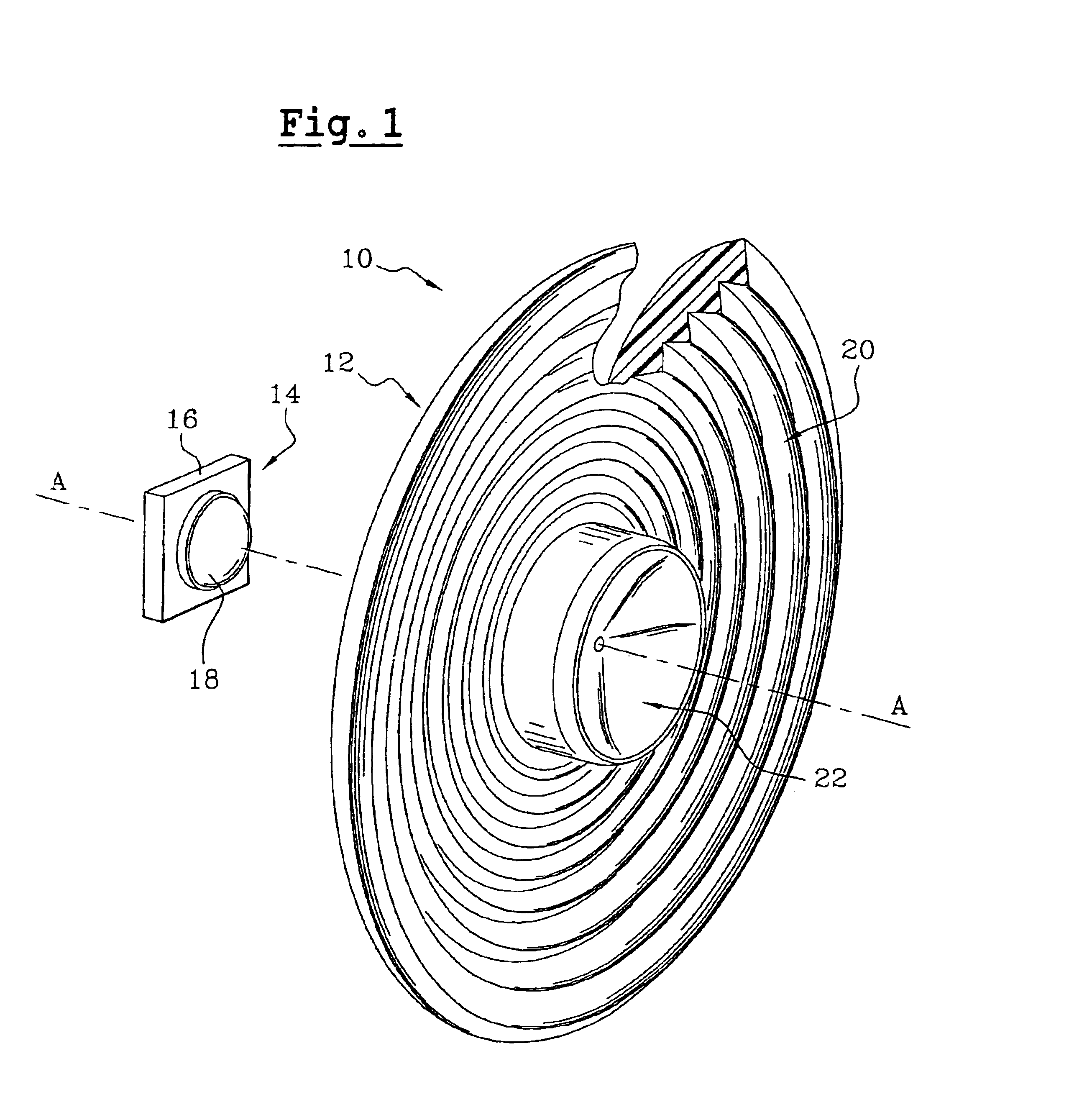
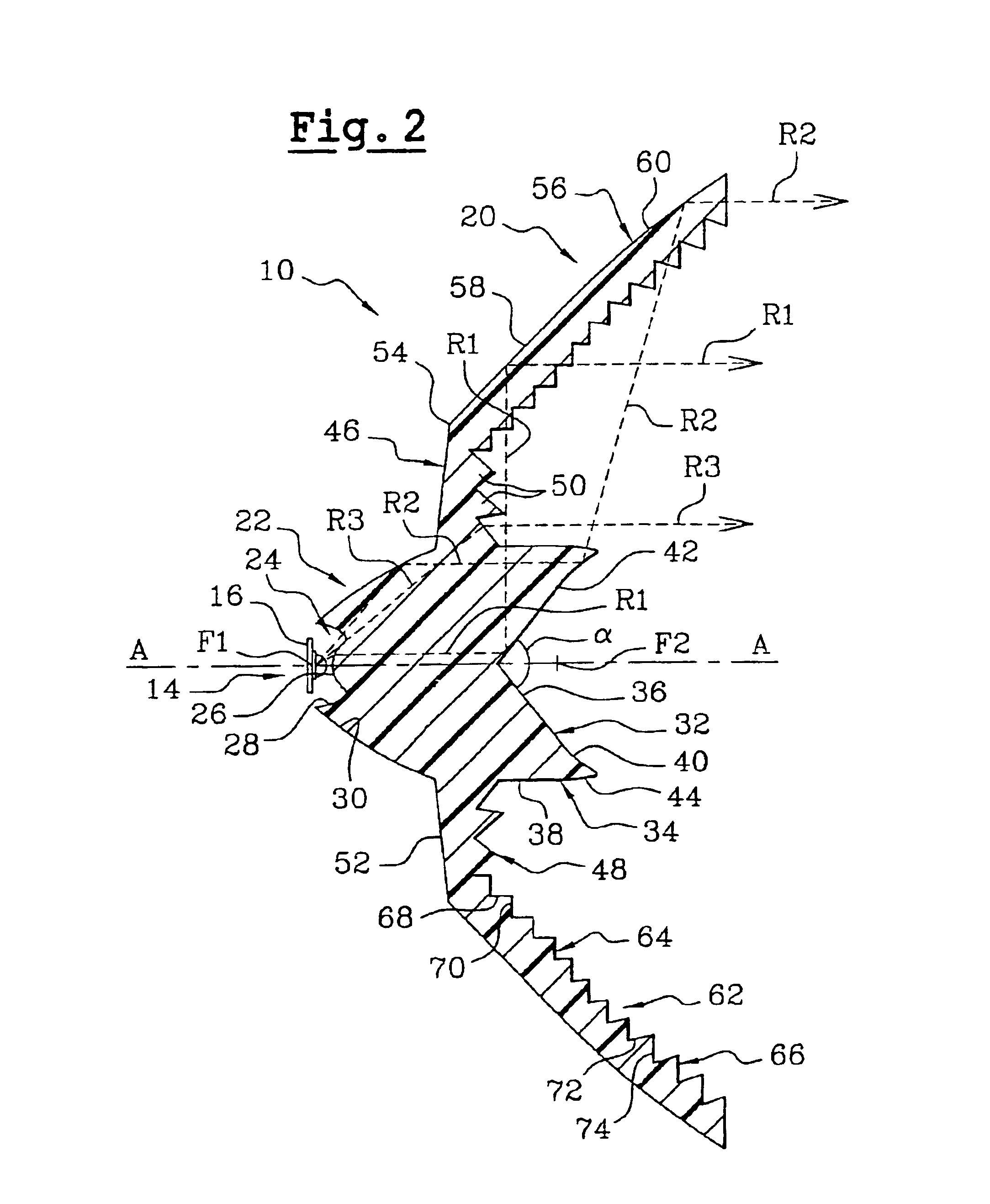
[0072]FIGS. 1 to 8 show an indicator lamp 10 which is produced in accordance with the invention.

[0073]The indicator lamp 10 comprises an optical device 12 for recovering and distributing the rays of light emitted by a light source 14, which is in this case formed by a light-emitting diode.

[0074]The optical device 12 here has an overall shape of revolution about an optical axis A—A.

[0075]In the rest of the description, an axial orientation from the rear to the front, which corresponds to an orientation from left to right on the optical axis A—A shown in FIG. 2, will be used in a non-limiting manner.

[0076]In a non-limiting manner, elements will be qualified as outer or inner depending on whether they are arranged radially towards the optical axis A—A or away from this axis.

[0077]The diode 14 is arranged on the optical axis A—A, behind the optical device 12.

[0078]The diode 14 has been shown mounted on a support board 16 which in particular allows it to be connected to an electrical pow...

second embodiment

[0161]A description will now be given, with reference to FIGS. 9 to 13, of an indicator lamp 10 that is produced in accordance with the invention.

[0162]The inlet face 24 of the light engine 22 in this case has a hemispherical shape, which is concave towards the front and is centred on the diode 14. The inlet face 24 is in this case complementary to the hemispherical globe 18 of the diode 14.

[0163]The light engine 22 comprises a rear reflection face 104 of generally parabolic shape, which is similar to the rear reflection face 30 of the first embodiment.

[0164]The focus F1 of the parabola corresponding to the rear reflection face 104 is in this case arranged at the centre of the diode 14, so that the rays of light, which enter the light engine 22 without being deflected, are reflected axially towards the front by the rear reflection face 104.

[0165]The light engine 22 comprises a front reflection face 32 of generally frustoconical shape, the vertex of the frustum of the cone being arra...

third embodiment

[0210]FIG. 14 shows an indicator lamp 10 which is produced in accordance with the invention.

[0211]This third embodiment comprises a coaxial annular reflector 20 which is, for example, of the same type as that described with reference to the second embodiment and to FIG. 10. The coaxial annular reflector 20 therefore comprises a series of reflection facets 124 arranged in the form of echeloned annuluses.

[0212]The third embodiment differs primarily in its light engine 22, which generally has the shape of a hollow hemispherical globe centred on the light source 14. The shape of the light engine 22 is in this case similar to that of an optical device known as a bonnet, which is commonly used in indicator lamps.

[0213]The concave rear face of the light engine 22 forms the inlet face 24 for the rays of light emitted by the source 14.

[0214]The convex front face of the light engine 22 forms, in its central part, a light diffusion face 132 and, in its peripheral part, an outlet face 134.

[0215...


PUM


Abstract

The invention proposes an indicator lamp comprising an optical axis oriented from the rear to the front, on which there is a light source which is provided for emitting a light flux towards the front, and of the type comprising an optical device for recovering and distributing the rays of light emitted by the source, with a view to providing an indicating faction that meets the regulations, wherein the optical device comprises a coaxial annular reflector and, in front of the light source a central optical part known as the light engine which is provided for distributing the rays of light emitted by the source in directions that are generally transverse about the optical axis, towards the coaxial annular reflector that is provided for distributing the rays of light axially towards the front.

Description

BACKGROUND OF THE INVENTION[0001]The invention proposes an indicator lamp, in particular for a motor vehicle.[0002]The invention more particularly proposes an indicator lamp, in particular for a motor vehicle, comprising an optical axis oriented from the rear to the front, on which there is a light source which is provided for emitting a light flux towards the front, at a solid angle centred on the axis, and of the type comprising an optical device for recovering and distributing the rays of light emitted by the source, with a view to providing, towards the front, an indicating function that meets the regulations, the optical device comprising a coaxial annular reflector and, in front of the light source, a central optical part known as the light engine which is provided for distributing the rays of light emitted by the source in directions that are generally transverse about the optical axis, towards the coaxial annular reflector that is provided for distributing the rays of light,...

Claims


Application Information

Patent Timeline
IPC IPC(8): F21V7/00F21S8/10F21V13/00F21V13/04F21S2/00F21V5/00F21V5/04F21W101/10F21Y101/02H01L33/44H01L33/48H01L33/58H01L33/60
CPCF21S48/215F21S48/2243F21S48/225F21S48/2268F21S48/2287F21S48/236F21S48/24F21V7/0091F21S48/1329F21Y2101/02F21Y2115/10F21S41/322F21S43/14F21S43/239F21S43/241F21S43/245F21S43/247F21S43/315F21S43/40
Inventor AYNIE, JEAN-PIERREGASQUET, JEAN-CLAUDE
Owner VALEO VISION SA
Why Eureka
Try Eureka