Apparatus for implantation into bone

a bone implant and bone technology, applied in the field of bone implanted apparatus, can solve the problems of bone screw dislocation of undesirably large bone, inability to withstand high tensile load without structural failure, and many of the known bone screw types, such as those described above, can be susceptible to toggling in the vertebral body and can pull out of the vertebral body

Inactive Publication Date: 2005-10-11
THE CLEVELAND CLINIC FOUND
View PDF47 Cites 183 Cited by
  • Summary
  • Abstract
  • Description
  • Claims
  • Application Information

AI Technical Summary

Problems solved by technology

The solid shank and external threads of the conventional bone screws can cause the bone screws to displace an undesirably large amount of bone when implanted.
The known corkscrew-style tissue anchors, when implanted, displace less bone than the conventional bone screws, but are generally not able to withstand high tensile loads without structural failure.
This structural weakness in the design of the screw in the EP 0 374 088 document is further compounded by the corkscrews having a larger overall diameter than the head of the screw where torque is applied.
One of the more challenging applications of a bone screw is implantation of the screw into the cancellous bone of a patient's spine or pelvis.
Unfortunately, many of the known bone screws, such as those described above, can be susceptible to toggling in the vertebral body and can also pull out of the vertebral body due to the substantial forces on the screws from human body movement and muscle memory.
However, use of such a nut increases the complexity of the surgical procedure.

Method used


Image

  • Apparatus for implantation into bone
  • Apparatus for implantation into bone
  • Apparatus for implantation into bone

Examples


third embodiment

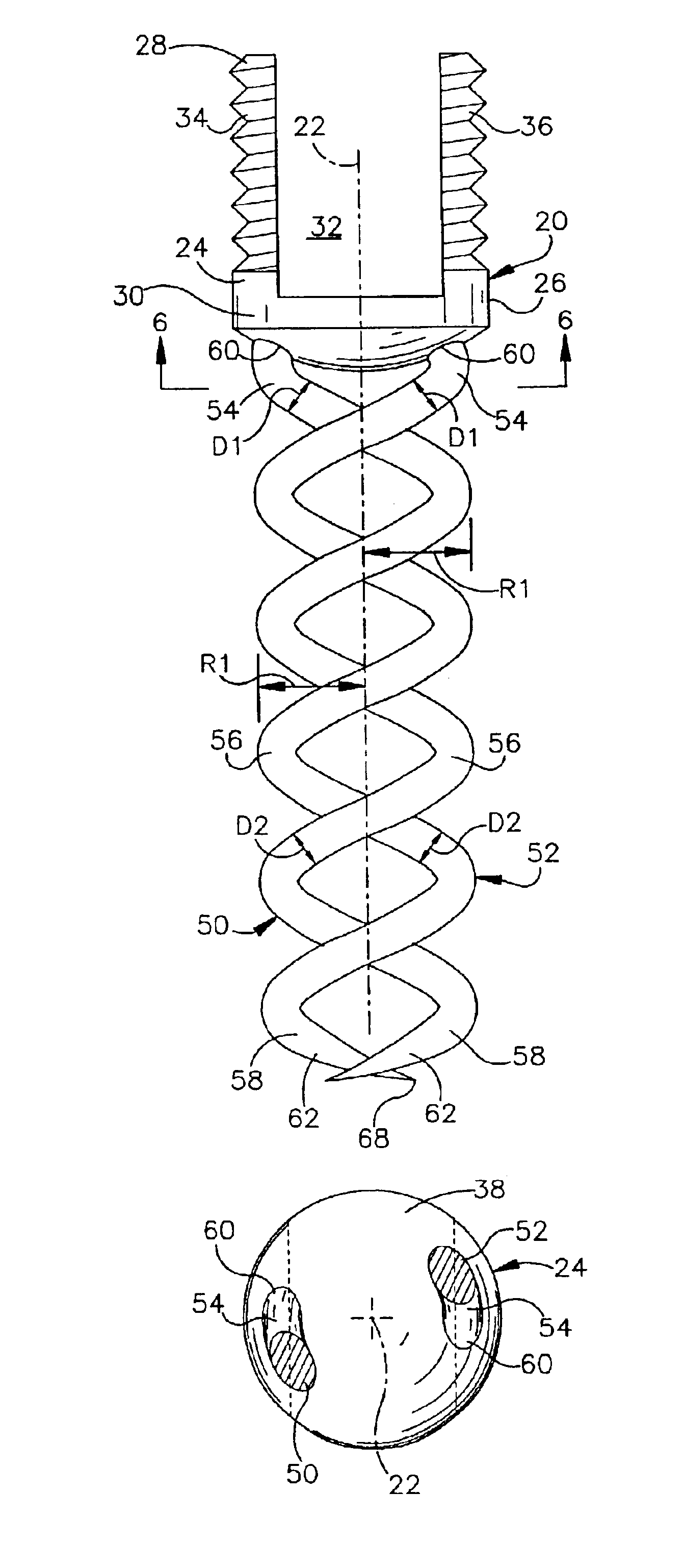
[0058] the apparatus 310 comprises an anchor 320 having a platform 324. The platform 324 has a threaded outer surface 330 adjacent a first end portion 332 and a cylindrical outer surface 340 adjacent a second end portion 342. The first end portion 332 of the platform 324 further includes an axial recess 334. The recess 334 has a hexagonal configuration for receiving a tool (not shown) for drivingly rotating the anchor 320. The first and second helical spikes 50 and 52 project from the end surface 38 of the platform 324.

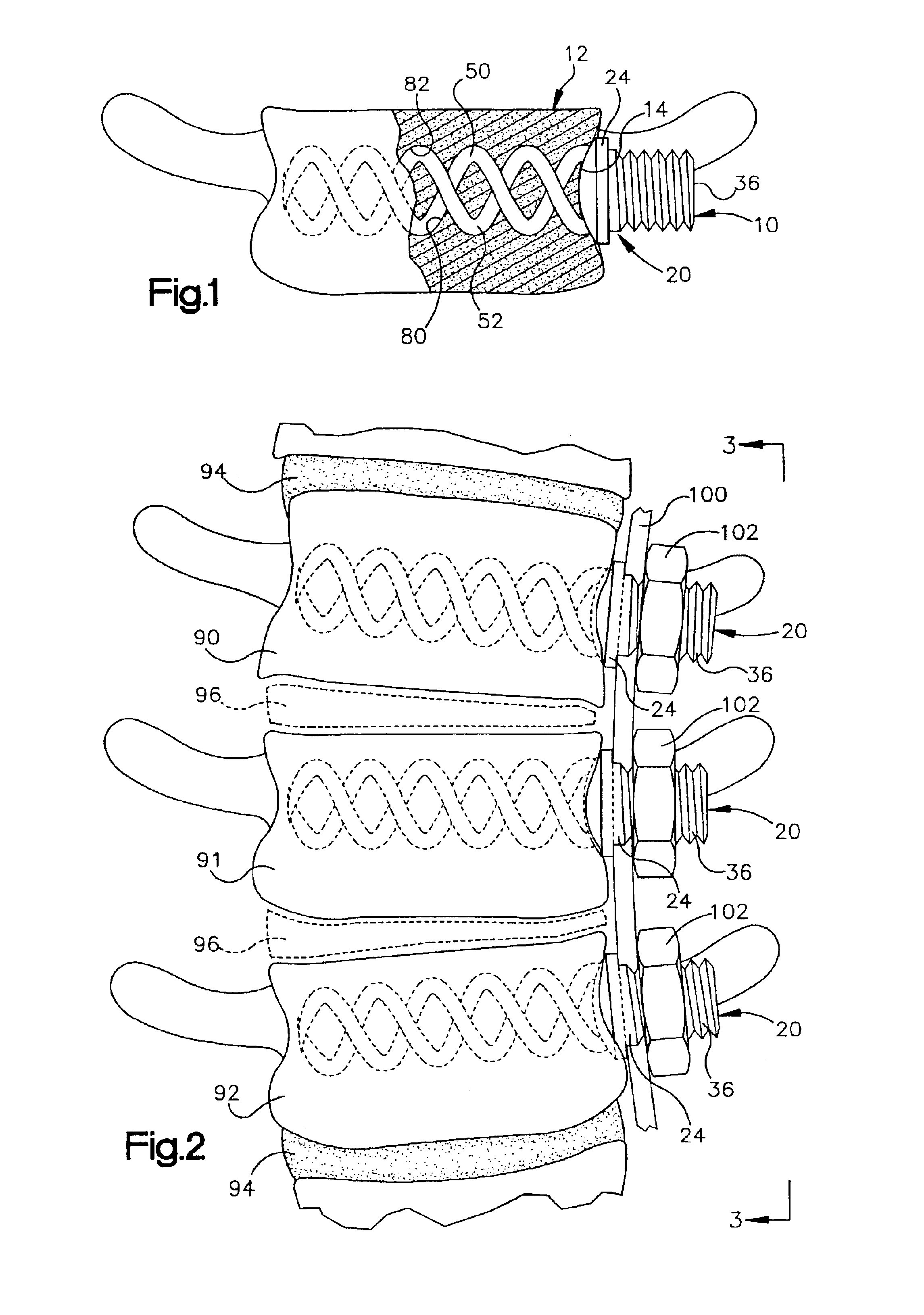
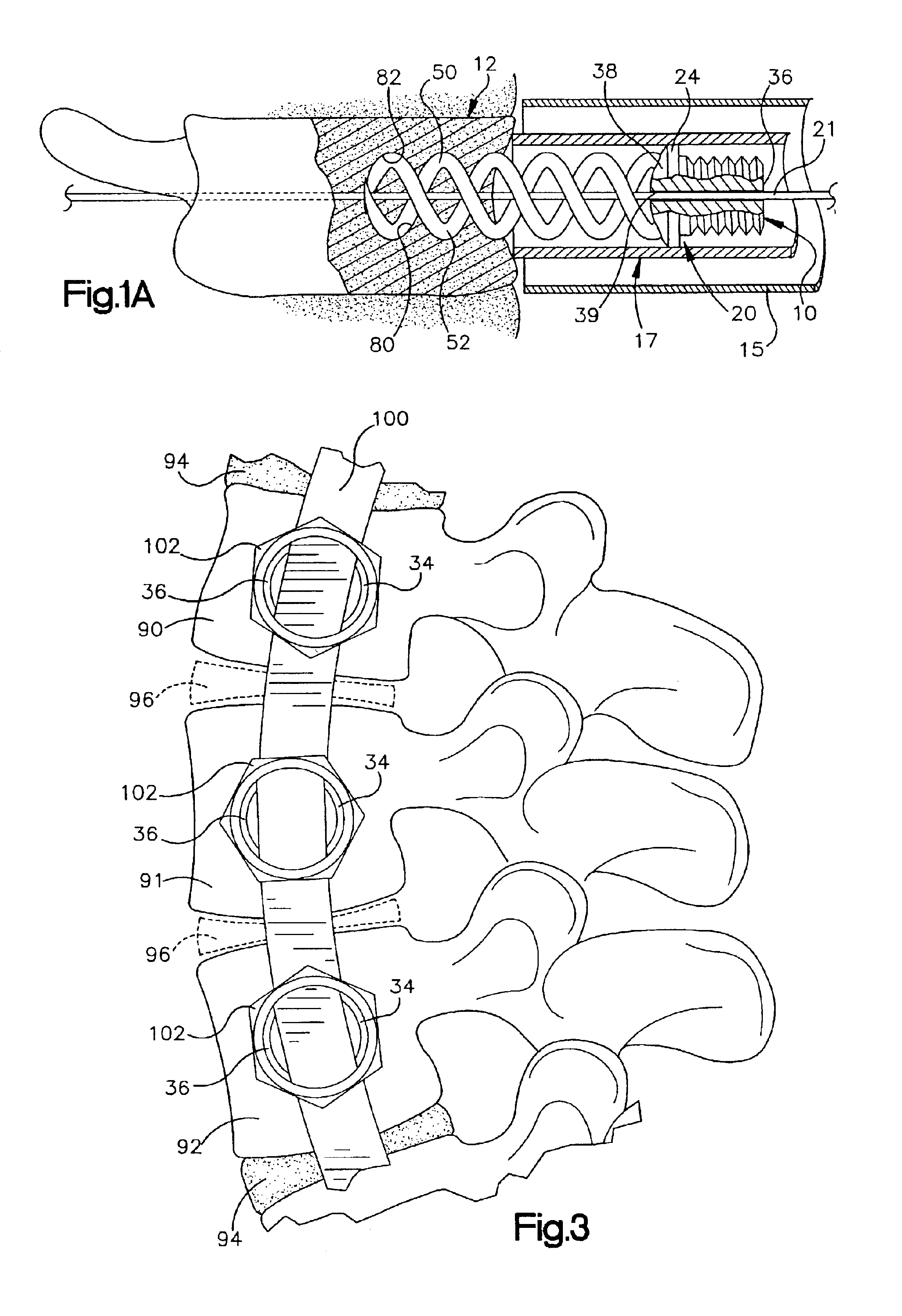
[0059]The apparatus 310 further includes a plate 350 and a nut 360. The plate 350 has a first opening 352 for receiving the portion of the platform 324 which has the threaded outer surface 330. The plate 350 has a second opening 354 for receiving a second anchor 320 (see FIG. 11) or other fixation instrumentation (not shown). When the anchor 320 is implanted in a vertebrae, the nut 360 screws onto the threaded outer surface 330 of the platform 324 to secure the plate ...

fourth embodiment

[0064]The apparatus 410 according to FIGS. 12 and 13 is particularly useful for a corpectomy application in which a damaged vertebrae is removed. As is shown in FIG. 12, after a portion of a damaged vertebrae 460 is removed, a first one of the pair of anchors 420 is implanted into a vertebrae 462 directly above the removed vertebrae 460 and a second one of the pair of anchors 420 is implanted into a vertebrae 464 directly below the removed vertebrae.

first embodiment

[0065]The anchors 420 are implanted in the vertebrae 462 and 464 in much the same manner as the anchor 20 according to the A rotatable tool (not shown) engages the planar surfaces 442 on the attachment tab 440 and rotates each of the anchors 420 to screw the helical spikes 450 and 452 of each of the anchors into the respective vertebrae 462 and 464. The anchors 420 are implanted so that they extend co-linearly along the axis 422. When implanted, the helical spikes 450 and 452 of the anchor 420 in the vertebrae 462 extend in an upward direction from the platform 430 of the upper (as viewed in the Figures) anchor, while the helical spikes 450 and 452 of the other anchor in the vertebrae 464 extend in a downward direction from the platform 430 of the lower (as viewed in the Figures) anchor.

[0066]A spinal fixation implant in the form of a cylinder member 480 connects the pair of anchors 420 to structurally support the vertebral column in the absence of the removed vertebrae 460. The cy...


PUM


Abstract

An anchor is implantable into a bone in a patient's body and, when implanted, is resistant to toggling in the bone and to being pulled from the bone. The anchor includes a head end portion having a surface that extends transverse to a central axis of the anchor and is engagable with the bone. A plurality of helical spikes extend from the surface on the head end portion and are engagable with the bone. Each of the plurality of helical spikes has a helical central axis that forms a helix around the central axis of the anchor. Each of the plurality of helical spikes further has a circular cross-sectional configuration as viewed in a plane extending perpendicular to the helical central axis of each of the helical spikes and a distal end portion with a tip that penetrates the bone as the head end portion is rotated relative to the bone.

Description

RELATED APPLICATIONS[0001]This application is a continuation-in-part of U.S. patent application Ser. No. 09 / 708,940, filed Nov. 8, 2000, now U.S. Pat. No. 6,551,322 which corresponds to U.S. Provisional Patent Application Ser. No. 60 / 238,271, filed Oct. 5, 2000, and which is assigned to the assignee of the present application.TECHNICAL FIELD[0002]The present invention is directed to an apparatus for implantation into a bone in a patient's body, and is particularly directed to an apparatus that, when implanted, is resistant to toggling in the bone and to being pulled from the bone.BACKGROUND OF THE INVENTION[0003]Bone screws are used in the medical field for a variety of purposes. Typical uses for bone screws, also referred as bone anchors, include treating a bone fracture, attaching a corrective device to parts of a fractured bone in an area adjacent to the fracture, and attaching a corrective device to a group of bones, such as vertebrae of a spinal column.[0004]Most known bone scr...

Claims


Application Information

Patent Timeline
Patent Type & Authority Patents(United States)
IPC IPC(8): A61B17/70A61F2/44A61B17/86A61B17/68A61F2/00A61F2/30A61B17/58A61BA61B17/16A61B17/88
CPCA61B17/1604A61B17/1671A61B17/70A61B17/7007A61B17/701A61B17/7032A61F2/44A61B17/7011A61B17/7055A61B17/869A61B17/888A61F2002/30224A61F2002/30235A61F2002/30289A61F2002/30401A61F2002/30428A61F2002/3085A61F2002/30853A61F2002/30856A61F2002/4475A61F2220/0025A61F2230/0069A61F2230/0091A61F2002/30593A61F2002/30851
Inventor LIEBERMAN, ISADOR H.
Owner THE CLEVELAND CLINIC FOUND
Why Eureka
Try Eureka