Method and devices for opto-electronically determining the position of an object

Inactive Publication Date: 2005-10-11
REIME GERD
View PDF11 Cites 39 Cited by
  • Summary
  • Abstract
  • Description
  • Claims
  • Application Information

AI Technical Summary

Benefits of technology

[0009]Proceeding from this state of the art, the object of the present invention is to make available a method and an appara

Problems solved by technology

Consequently, the displacement and/or position of the object cannot be freely determined.
These discriminators, however, have relatively long delay times (10 seconds, or respectively 0.1 to 0.6 seconds)

Method used


Image

  • Method and devices for opto-electronically determining the position of an object
  • Method and devices for opto-electronically determining the position of an object
  • Method and devices for opto-electronically determining the position of an object

Examples


Example

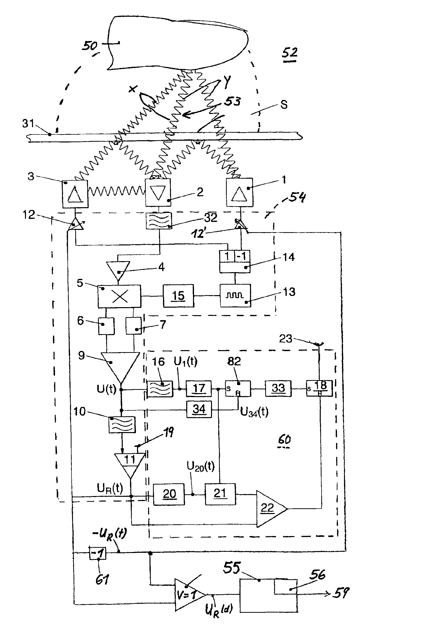
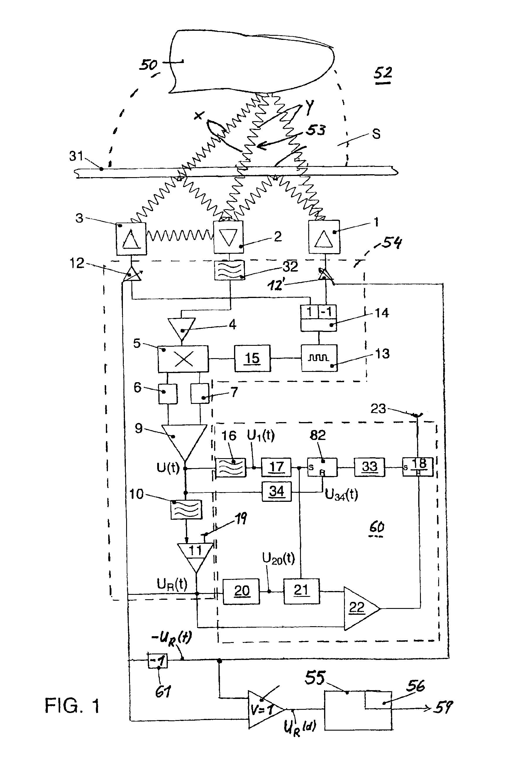
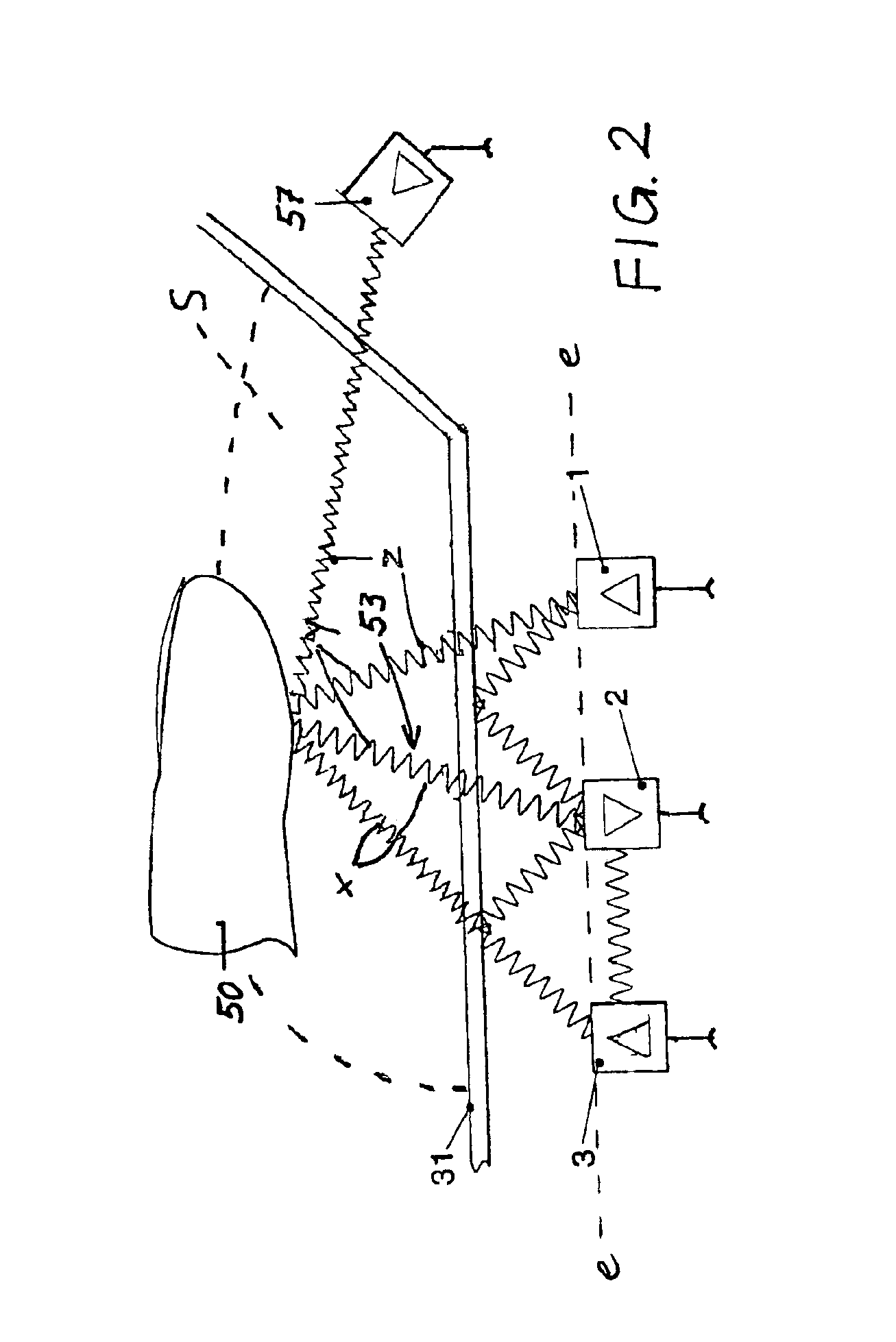
[0031]The invention is now explained in more detail with reference to the enclosed drawings. However, the exemplified embodiments are only examples and are not to restrict the inventive concept to a specific arrangement.

[0032]The exemplified embodiments show various developments of an opto-electronic apparatus for determining the position of an object 50 through the intermediary of a measuring arrangement, which is separated from the object 50 by a medium 31, 52, which is permeable to at least one specific radiation. The apparatus is equipped with at least two light emitting sources of radiation 1, 3, 57 and at least one radiation receiver 2. The radiation receiver 2 passes its signals, the value of which depends on the amount of light received, to an evaluation unit 55. Sources of radiation 1, 3, 57 and radiation receiver 2 can be disposed in such a manner that the light emitted by the transmitting member is dispersed or reflected by objects, which are situated within a certain act...


PUM


Abstract

The invention relates to a method and a device for opto-electronically determining the position of an object (50) using a measurement assembly, which is separated from the object (50) by a medium (31, 52) that is permeable to at least one type of specific radiation. The measurement assembly consists of at least one active sensor zone (S) in the medium comprising at least two measuring paths (x, y), which are maintained by at least two radiation sources (1, 3) that emit the specified radiation and by at least one radiation receiver (2) that is allocated to the radiation sources. Said receiver determines the reflection (53) returned by the object (50) to generate a detection signal which corresponds to the received radiation. A specified radiation is emitted using the radiation sources (1, 3) and the reflection (53) returned by the object (50) is detected, in order to allocate initial values (U(t), UR(d)) to the individual measuring paths. The invention is characterised in that an evaluation unit (55) determines the position and/or displacement of the object (50) by determining a specified angular curve of the object in relation to the radiation sources (1, 3, 57) from the initial value (UR(T), UR(d)), for a known spatial relationship between the radiation sources. This allows the position and/or displacement of an object to be opto-electronically detected in a simple and practical manner.

Description

REFERENCE TO RELATED APPLICATIONS[0001]The present application claims the priority of German Patent Application 100 24 156.5, submitted on May 19, 2000, the disclosure contents of which are hereby expressly also made the object of the present Application.[0002]1. Field of the Invention[0003]The invention relates to a method for opto-electronically determining the position of an object in accordance with the main preamble of claim 1 as well as an apparatus for carrying out the method in accordance with the main preamble of claim 3.[0004]2. State of the Prior Art[0005]A method of this type and an apparatus of this type are known in EP 0 706 648 B1. The apparatus there is preferably used for the detection of water droplets on a pane of glass, it being possible to control a windscreen wiper in dependence on the droplets determined. Two measuring paths are set up for this purpose between one radiation source and one radiation receiver. Whilst the radiation source emits the radiation, the...

Claims


Application Information

Patent Timeline
IPC IPC(8): G01S5/16G01S3/783G01S17/06G01S3/78G01S5/00G01S17/00G01S17/87G01S7/48G01S7/487
CPCG01S3/783G01S5/16G01S17/06G01S17/87G01S7/487G01S7/497
Inventor REIME, GERD
Owner REIME GERD
Why Eureka
Try Eureka