
Trap circuit arrangement

a circuit arrangement and circuit technology, applied in the direction of transmission, inductance, inductance with magnetic core, etc., can solve the problems of comparatively expensive manufacturing or assembly, and achieve the effect of cost-effective manufacturing and assembly

Active Publication Date: 2005-10-11
MD ELEKTRONIK
View PDF6 Cites 7 Cited by
  • Summary
  • Abstract
  • Description
  • Claims
  • Application Information

AI Technical Summary

Benefits of technology

"The present invention provides a trap circuit arrangement that is cost-effective and easy to assemble. The arrangement includes a housing made up of two assembled parts that can be attached to an attachment surface, such as a panel of a motor vehicle. The housing has at least one clip element that interacts with the clip element of the housing to mount the housing to the attachment surface in a prestressed manner. The arrangement also includes a choke coil with helix-shaped windings and connection regions that can be connected to cables. The housing can be formed of two assembled parts with recesses to allow for the cables to pass through. The clip element and the spring element can be integral components of the housing or separate parts that are assembled together. The technical effects of the invention include a cost-effective and easy-to-assemble trap circuit arrangement that can be attached to various surfaces and can be used in various applications."

Problems solved by technology

Conventional designs of trap circuit arrangements having a choke coil, in particular those used in motor vehicles, have, inter alia, the disadvantage that they are comparatively expensive to manufacture or assemble.

Method used


Image

  • Trap circuit arrangement
  • Trap circuit arrangement
  • Trap circuit arrangement

Examples


Embodiment Construction

[0032]In the represented exemplary embodiment, a trap circuit arrangement is described, as it is used in a circuit for heating a rear window of a motor vehicle. In this context, the rear window has wires, which are simultaneously used as an antenna for receiving radio signals in the FM and AM frequency-band ranges.

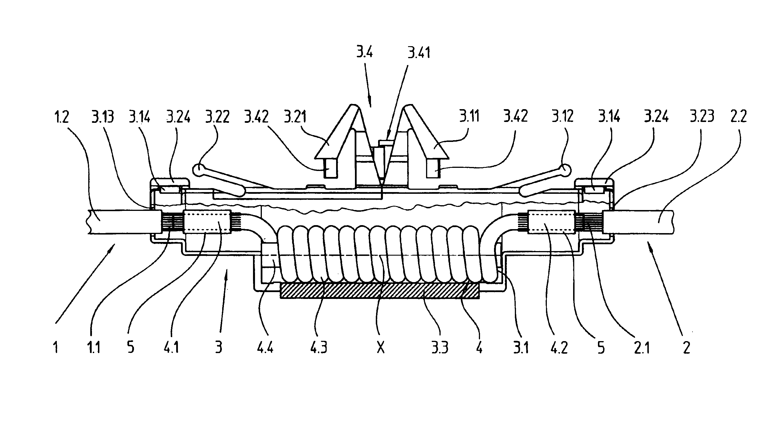
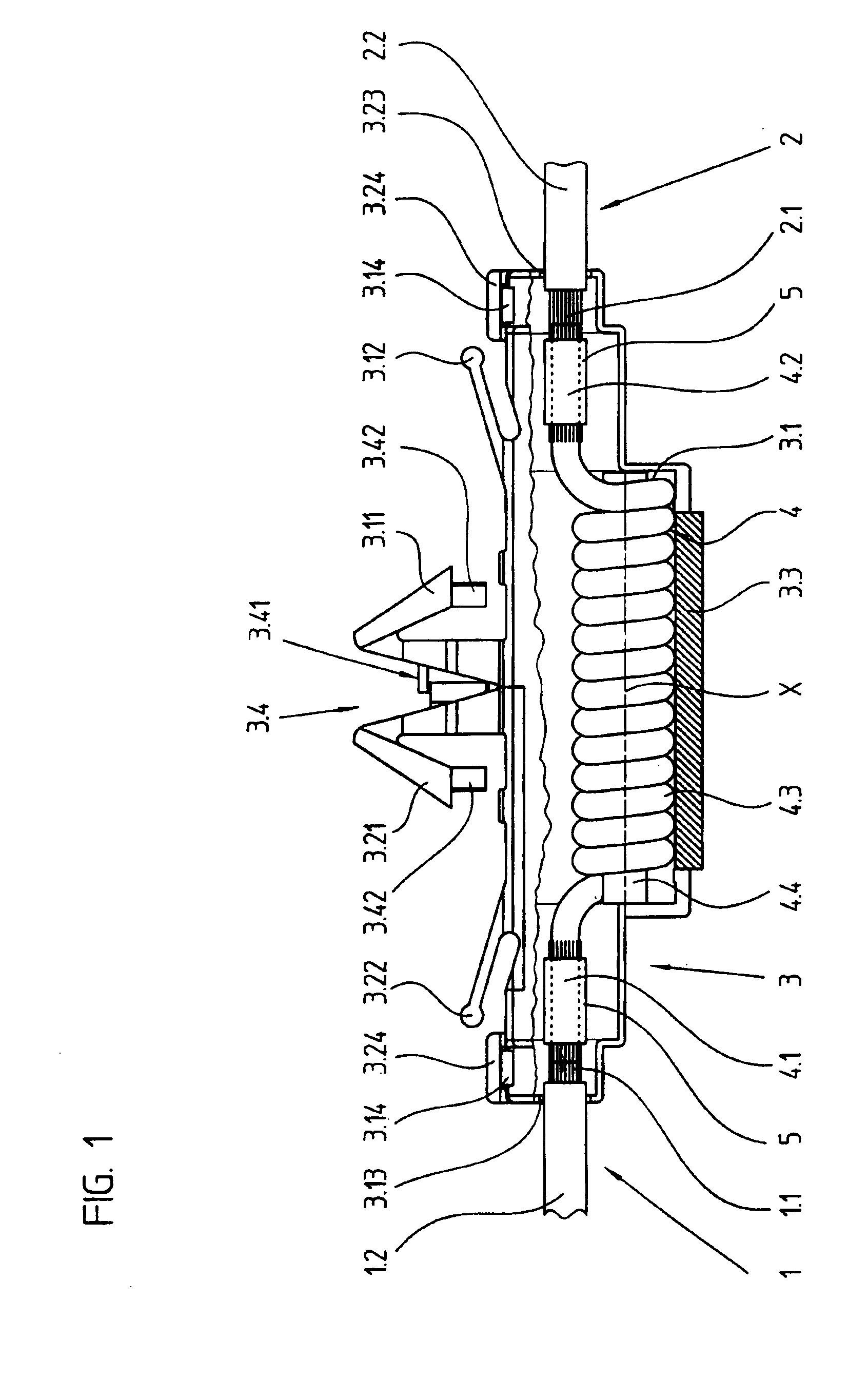
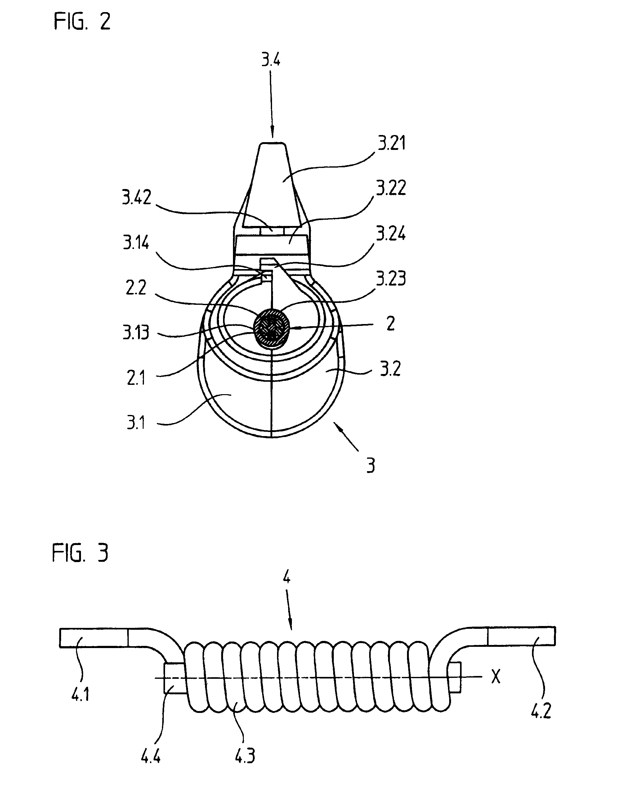
[0033]Shown in FIG. 1 is a side view having a partial sectional view of a trap circuit arrangement according to an example embodiment of the present invention. The trap circuit arrangement includes two cables 1, 2, which have several copper strands 1.1, 2.1 as conductors, the copper strands being surrounded by a plastic sheath 1.2, 2.2 for providing electrical insulation (see also FIG. 2). Also belonging to the trap circuit arrangement is a housing 3, which encloses a choke coil 4 and is described in detail further below. Choke coil 4 is made up of a copper wire, which is provided with insulating varnish and is bent about central axis X along a cylindrical helix in a large...


PUM

PropertyMeasurementUnit
frequencyaaaaaaaaaa
inductanceaaaaaaaaaa
electrical insulationaaaaaaaaaa

Abstract

A trap circuit arrangement, e.g., for an antenna line in a motor vehicle, includes a first and a second cable and a choke coil. In this context, the choke coil has a first and a second connection region, the first cable being in electrical contact with the first connection region and the second cable being in electrical contact with the second connection region. The trap circuit arrangement also includes a housing, which accommodates the choke coil, is made up of two assembled parts, and has at least one clip element on its exterior for attachment to an attachment surface.

Description

CROSS-REFERENCE TO RELATED APPLICATIONS[0001]The present application claims priority to Application No. 203 17 509.3, filed in the Federal Republic of Germany on Nov. 13, 2003, which is expressly incorporated herein in its entirety by reference thereto.FIELD OF THE INVENTION[0002]The present invention relates to a trap circuit arrangement, which has a choke coil in a housing and may be particularly suitable for installation in motor vehicles.BACKGROUND INFORMATION[0003]In modern motor vehicles, it is not rare for wires that heat rear windows to be simultaneously used as an antenna for receiving high-frequency signals. In order that, for example, starting pulses of the rear-window heater do not interfere with the received signals, choke coils having a corresponding inductance are often built into the supply line. To prevent damage, such choke coils must be protected, as a rule, from external influences, i.e., must be provided with electrical insulation.[0004]In conventional arrangeme...

Claims


Application Information

Patent Timeline
Patent Type & Authority Patents(United States)
IPC IPC(8): H01F27/29H01F27/02H01Q1/12H01F17/04H05K7/12
CPCH01F17/045H01F27/027H01F27/29H01Q1/1278H05K7/12
Inventor FRIESE, NORBERTMAYR, JOSEF
Owner MD ELEKTRONIK
Learn More