Actuator with transmission element

a technology of transmission element and actuator, which is applied in the direction of basic electric elements, electrical apparatus, and electric motors, can solve the problems of high cost of assembly, mounting and mounting the actuator, and manufacturing its individual parts, and achieves cost-effective manufacturing and assembly.

Active Publication Date: 2017-05-23
SCHAEFFLER TECH AG & CO KG
View PDF10 Cites 0 Cited by
  • Summary
  • Abstract
  • Description
  • Claims
  • Application Information

AI Technical Summary

Benefits of technology

[0006]It is an object of the present invention to provide an actuator which is suitable for a sliding cam system and is cost-effective to manufacture and to assemble.
[0007]The actuator according to the present invention includes at least one electromagnet, a magnet housing, at least one thrust pin and at least one movable armature having a plunger which is movable in an axial direction. When the at least one electromagnet is energized, an axial movement of the at least one armature is transmittable to the at least one thrust pin via the at least one plunger. The actuator also includes at least one lever which is supported pivotably to one side in the magnet housing. The at least one lever is operatively connected to the at least one plunger and the at least one thrust pin in such a way that the axial movement of the at least one plunger is transmittable to the at least one thrust pin. In particular, the at least one plunger abuts the lever for the purpose of transmitting force. The actuator is suitable for activating a sliding cam system. A lever in the actuator which is designed and situated in this way has the advantage that it is cost-effective to manufacture and to assemble.
[0013]In one preferred specific embodiment, the second lever end has a convex indentation, and / or the first end of the assigned thrust pin has a convex elevation. Due to this design, no planar contact exists between the thrust pin and the assigned lever, but rather (ideally) only a contact at one point or on a line. The design according to the present invention of the contact between the lever and the thrust pin has the advantage that a reliable and better transmission of force from the lever to the thrust pin is implemented, which is independent of the lever position. In addition, the support area of the lever is designed as a trough-like indentation. Due to this design, the plunger abuts the lever in a stable manner, and the plunger is always in the correct working position. The convex surface and the trough-like indentation on the lever may be easily and cost-effectively manufactured on the formed lever. A convex surface on the first end of the thrust pin may likewise be easily and cost-effectively manufactured.
[0015]If the position of the support area on the lever is set in such a way that the two strokes are of the same length (transmission ratio 1:1), the size of movement of the plunger is completely converted into a movement of equal size of the corresponding thrust pin. The lever is preferably a rigid lever, since this prevents energy from being lost in the form of a deformation.
[0016]The position of the support area of the lever is, however, ideally set in such a way that the armature stroke is smaller compared to the thrust pin stroke, corresponding to the lever ratio set in this manner. Due to the smaller armature stroke, the particular solenoid coil may have a compact design, and thus the magnet housing, including it's at least one electromagnet, may also have a more compact design than that of a specific embodiment in which the at least one armature covers the complete thrust pin stroke. In the case of a small armature stroke, the actuator may have a compact design. A transmission ratio of approximately two has proven to be advantageous, the length of the stroke of the thrust pin thus being approximately twice the length of the stroke of the assigned armature. However, other transmission ratios may also be implemented.

Problems solved by technology

The disadvantage of the actuator is that the stop valve and the flexible tongue are delicate and high-precision components, which makes it expensive to mount the actuator and to manufacture its individual parts.
The disadvantage of the actuator is that the additional supporting spring, the latching device and the rocker also represent a delicate and high-precision arrangement, which also makes it expensive to assemble and mount the actuator and to manufacture its individual parts.

Method used


Image

  • Actuator with transmission element
  • Actuator with transmission element
  • Actuator with transmission element

Examples


Embodiment Construction

[0022]Identical reference numerals are used for the same elements or elements having the same function. Furthermore, for the sake of clarity, only reference numerals which are necessary for describing the particular figure are shown in the individual figures. The illustrated specific embodiments only represent examples of how the actuator according to the present invention may be designed and do not represent a final limitation of the present invention.

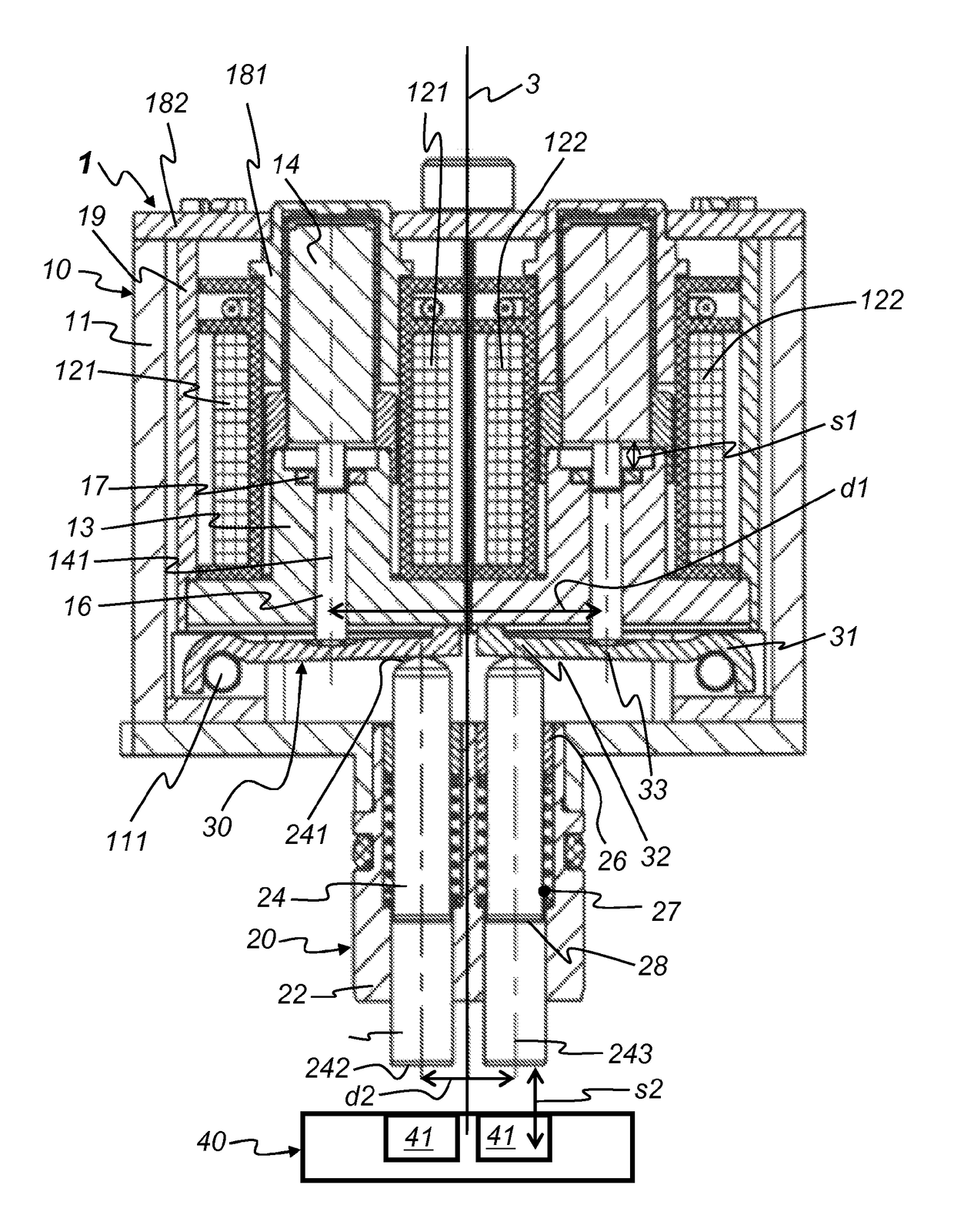
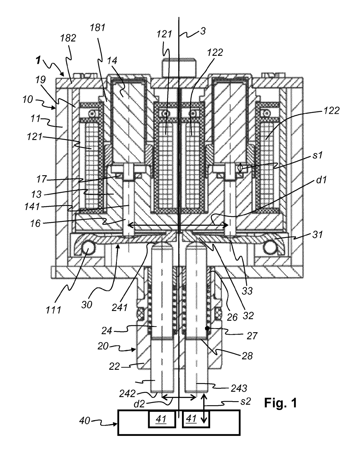
[0023]FIG. 1 shows a schematic representation of an actuator 1 according to one specific embodiment of the present invention. The actuator essentially includes an electromagnet unit 10 and a thrust pin unit 20.

[0024]Electromagnet unit 10 includes at least one electromagnet 121, 122, 13, 14, 16, 17, 181, 182, 19 and a magnet housing 11. Each electromagnet usually includes a solenoid coil 121 and 122, a magnetic yoke, which in this case is optionally designed as a unit of a yoke sleeve 181 and a yoke disk 182, an optional return path el...


PUM

PropertyMeasurementUnit
axial movementaaaaaaaaaa
thrustaaaaaaaaaa
areaaaaaaaaaaa

Abstract

An actuator (1) including at least one electromagnet (121, 122, 13, 14, 16, 17, 181, 182, 19, a magnet housing (11), at least one thrust pin (24) and at least one movable armature (14) with a respective plunger (16) that is movable in an axial direction is provided. When the at least one electromagnet (10) is energized, an axial movement of the at least one armature (14) can be transmitted via the at least one plunger (16) to the at least one thrust pin (24). At least one lever (30) is provided which is pivotably mounted on one side in the magnet housing (11) and with which at least one plunger (16) and the at least one thrust pin (24) are operatively connected such that the axial movement of the at least one plunger (16) can be transmitted to the at least one thrust pin (24).

Description

[0001]The present invention relates to an actuator. The actuator includes at least one electromagnet, a magnet housing, at least one thrust pin and at least one movable armature having a plunger which is movable in an axial direction. When the at least one electromagnet is energized, and axial movement of the at least one armature is transmittable to the at least one thrust pin via the at least one plunger.BACKGROUND[0002]Actuators, which are also referred to as “converters,”“drive elements,” and “adjusting devices,” are known from the prior art. In particular, actuators are also known which convert electrical signals for at least one electromagnet into mechanical movement of an armature connected thereto. The armature, in turn, transmits at least part of the mechanical movement to a plunger, push rod or armature rod. The plunger (or push rod or armature rod) transmits at least part of the mechanical movement to at least one thrust pin, also referred to as a drive pin. The thrust pi...

Claims


Application Information

Patent Timeline
Patent Type & Authority Patents(United States)
IPC IPC(8): H01F7/17H01F7/08F01L13/00H01F7/16
CPCH01F7/08F01L13/0036H01F7/1607H01F7/17F01L2013/0052F01L2013/101F01L2820/031
Inventor STEIGERWALD, MARTINHOPPE, JENSKONIAS, STEFAN
Owner SCHAEFFLER TECH AG & CO KG
Why Eureka
Try Eureka