Basement window shield with integrated vent

a window well and base technology, applied in ventilation systems, heating types, lighting and heating apparatus, etc., can solve the problems of obstructing the view out of the window, damage to the accompanying building, and condensation inside the cover, so as to reduce the need for moving parts and their associated maintenance

Inactive Publication Date: 2005-10-18
MEISSNER STEPHEN D
View PDF21 Cites 5 Cited by
  • Summary
  • Abstract
  • Description
  • Claims
  • Application Information

AI Technical Summary

Benefits of technology

[0008]The invention includes a window well cover that protects window wells from collecting debris and from the elements as well as protecting people and animals from accidental entry while allowing continuous airflow. Additionally, the window well cover provides the aforementioned protection and airflow while alleviating the need for movable parts and their associated maintenance.

Problems solved by technology

However, such window well covers are typically not vented and as a result, in humid climates, condensation can form inside the cover and obstruct a view out of the window.
Further, a build up of condensation within the window well cover can, over time, cause damage to the accompanying building.
Similarly, such window covers do not allow ventilation into the building through the covered window.
Additionally, it is impractical to remove the cover to alleviate a build up of moisture within the cover or to allow airflow through the window because such window covers are permanently attached.
However, such assemblies add to the complexity of the design by including multiple interconnected pieces, much like a door and hinge assembly.
Furthermore, in such window covers having movable venting means, it is necessary to physically open and close the vent when desiring airflow or protection from the elements.
The inclusion of multiple pieces not only adds to production costs but when exposed to the harsh conditions of the elements, these additional parts are susceptible to breakdown and often require upkeep and management to maintain consistent operation.

Method used


Image

  • Basement window shield with integrated vent
  • Basement window shield with integrated vent
  • Basement window shield with integrated vent

Examples


Embodiment Construction

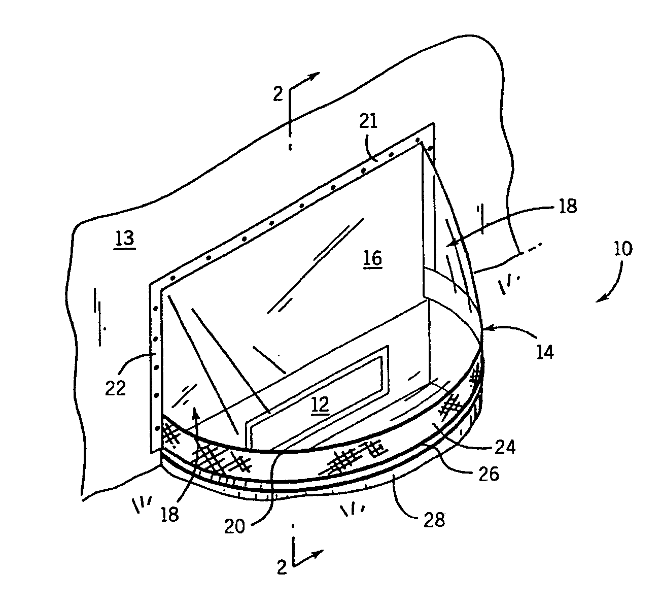
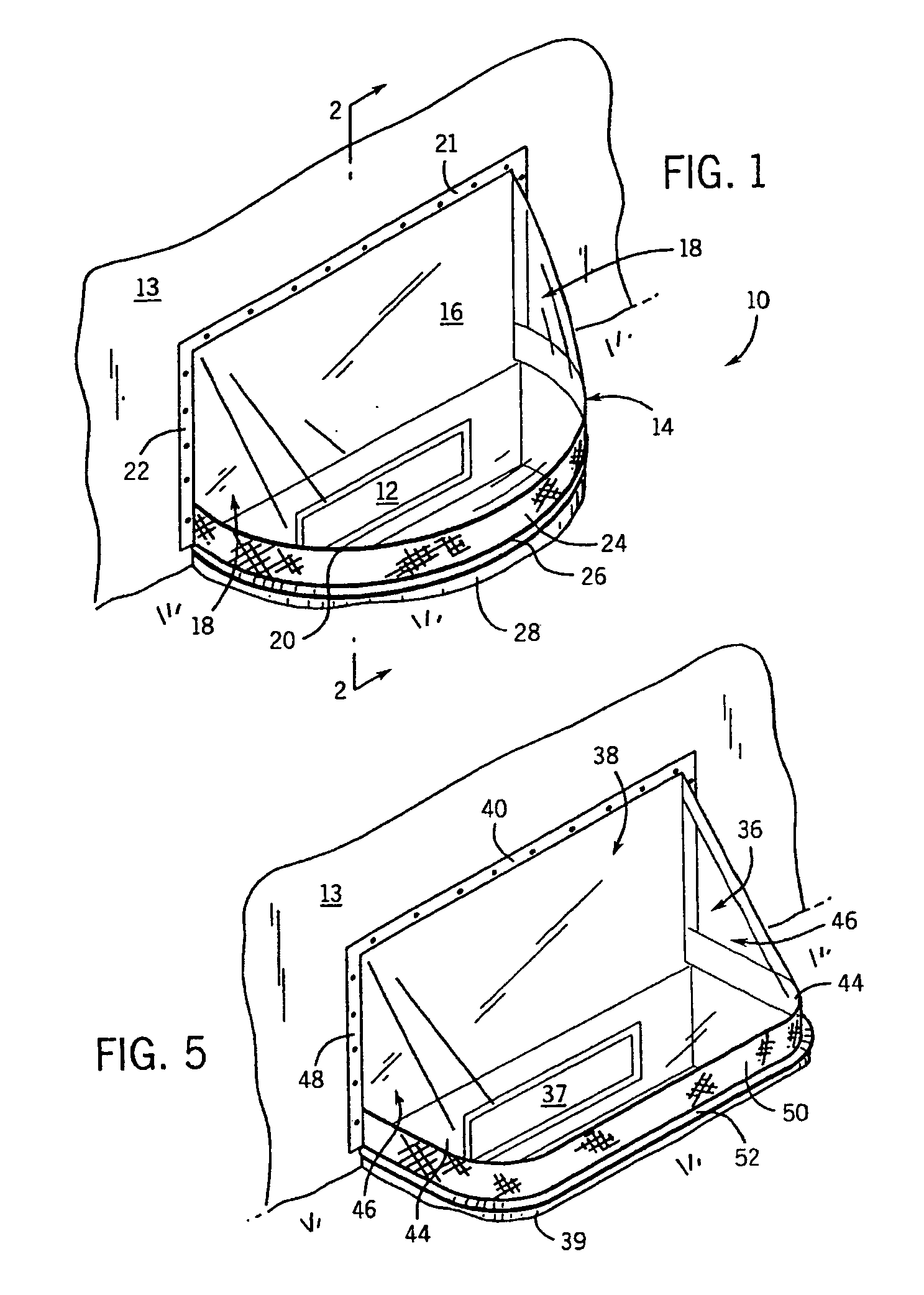
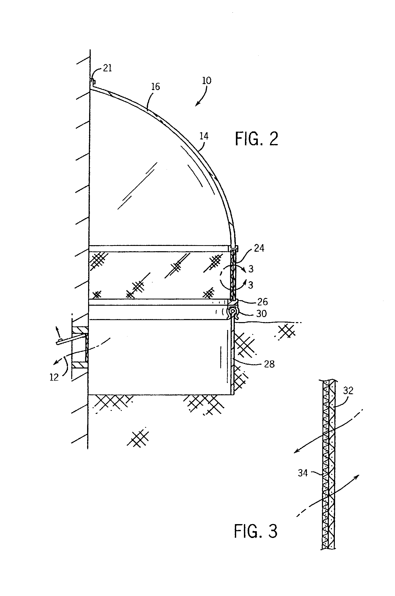
[0021]Referring to FIG. 1, a window well cover 10 is shown in accordance with one embodiment of the present invention. The window well cover 10 is designed to cover a below-grade window 12 of a building or other structure 13. The window well cover 10 includes a transparent upper structure 14 having a dome shape, that forms the upper end of the window well cover 10 and is comprised of a weather-impervious material. Preferably, the dome portion 14 is formed of plastic, glass or another weather-impervious material that is preferably transparent. Using a transparent material allows a line of sight as viewed from inside the covered window out beyond the window well cover 10 through the dome portion 14 and allows light entry through the dome 14, below-grade window 12 and into the building or structure 13. However, it is contemplated that the dome portion 14 could be constructed of an opaque material in order to restrict light entry through the window well cover 10 if desired. Additionally...


PUM


Abstract

A window well cover for a below-grade or basement window is disclosed. A transparent upper structure or portion is designed to cover a below-grade window on an outside of a building or other structure. The upper end of the transparent upper structure extends, or is angled, downwardly from a mounting flange terminating at a lower end. Furthermore, the transparent upper structure has two curved sides, which serve to connect the side ends. Mounting flanges extend outwardly from the two side ends. The window well cover includes a vent portion integrally formed therewith of an air pervious material to allow continuous air exchange through the window well cover. The vented portion may extend the length of, or the entire lower periphery of, the transparent upper structure. The window well cover, which is free of movable parts, allows for continuous airflow through the window well cover while restricting the entry of debris and insects.

Description

BACKGROUND OF INVENTION[0001]The present invention relates generally to a cover for window wells, and more specifically, to a cover for window wells that is vented to allow airflow through the window cover. Further, the venting is achieved without moving parts.[0002]Typically, window well covers have been single-piece construction for the purpose of protecting a window well and accompanying window from dirt, animals, leaves and other debris. By enclosing the window well with this single-piece cover, typically constructed of plastic, and securing the cover to the building or ground, the window well is further protected from the elements.[0003]However, such window well covers are typically not vented and as a result, in humid climates, condensation can form inside the cover and obstruct a view out of the window. Further, a build up of condensation within the window well cover can, over time, cause damage to the accompanying building. Similarly, such window covers do not allow ventilat...

Claims


Application Information

Patent Timeline
Patent Type & Authority Patents(United States)
IPC IPC(8): E06B5/00E06B5/02E04F17/06E06B5/01
CPCE04F17/06E06B5/01E06B5/02
Inventor MEISSNER, STEPHEN D.
Owner MEISSNER STEPHEN D
Why Eureka
Try Eureka