Fuel container for a motor vehicle

a technology for fuel containers and motor vehicles, applied in the direction of machines/engines, positive displacement liquid engines, separation processes, etc., can solve the problems of large amount of fuel movement and high level of permeation of fuel into the surroundings of fuel containers, and achieve the effect of reducing the effort involved

Active Publication Date: 2005-10-18
CONTINENTAL AUTOMOTIVE GMBH
View PDF14 Cites 29 Cited by
  • Summary
  • Abstract
  • Description
  • Claims
  • Application Information

AI Technical Summary

Benefits of technology

[0005]This problem is solved according to the invention in that in each of a plurality of chambers there is arranged a filling level sensor for determining the filling level of fuel in the respective chamber, and in that means for reducing the feeding of fuel to the suction jet pump located in a virtually empty chamber are provided.
[0006]As a result of this design, the feeding capacity with one or more empty chambers of the fuel container can be reduced in such a way that the suction jet pumps receive less fuel, or no fuel at all. The reduction of the feeding of fuel to the suction jet pumps leads to a reduction in the movement of the fuel in the fuel container. It is not necessary to arrange a suction jet pump with a filling level sensor in each individual chamber. It may be sufficient if suction jet pumps and filling level sensors are arranged in some of the chambers.
[0007]The means for reducing the feeding are embodied, according to one advantageous development of the invention, in a particularly simple structural way if the control unit is designed to reduce the feeding capacity of the feeding unit when a chamber is virtually empty. As a result, the feeding capacity of the feeding unit can be adapted as a function of the filling level of fuel in the respective chambers of the fuel container according to the invention.
[0008]According to one advantageous development of the invention, the control unit is capable of determining the filling levels of the individual chambers separately and regulating the feeding capacity of the feed unit as a function of the filling levels if a filling level sensor is arranged in each of the chambers and if the filling level sensors are individually connected to the control unit. This design has the advantage that a suction jet pump which is provided in the first chamber for filling a surge chamber of the feeding unit also receives less fuel or no fuel if the first chamber is empty.
[0013]According to another advantageous development of the invention, the suction jet pumps can each easily be combined with a filling level sensor and the valve to form one structural unit if the valve can be switched by a float of the filling level sensor. In the simplest case it is sufficient to connect a closing element of the valve to the float via a linkage. This contributes to reducing the effort involved in mounting the fuel container according to the invention.
[0014]According to another advantageous development of the invention, the feeding unit can easily be prevented from running dry when there is a defect in the filling level sensors by using means for switching over the feeding unit to maximum pumping capacity and / or for opening the valve arranged in the propellant line when there is a failure of one of the filling level sensors.

Problems solved by technology

A disadvantage with the known fuel container is that a large amount of fuel is moved to the fuel container as a result of the feeding capacity of the feeding unit which is defined by the number of suction jet pumps.
This movement leads to the formation of foam and to increasing vaporization of the fuel, which results in a high level of permeation of the fuel into the surroundings of the fuel container.

Method used


Image

  • Fuel container for a motor vehicle
  • Fuel container for a motor vehicle
  • Fuel container for a motor vehicle

Examples


first embodiment

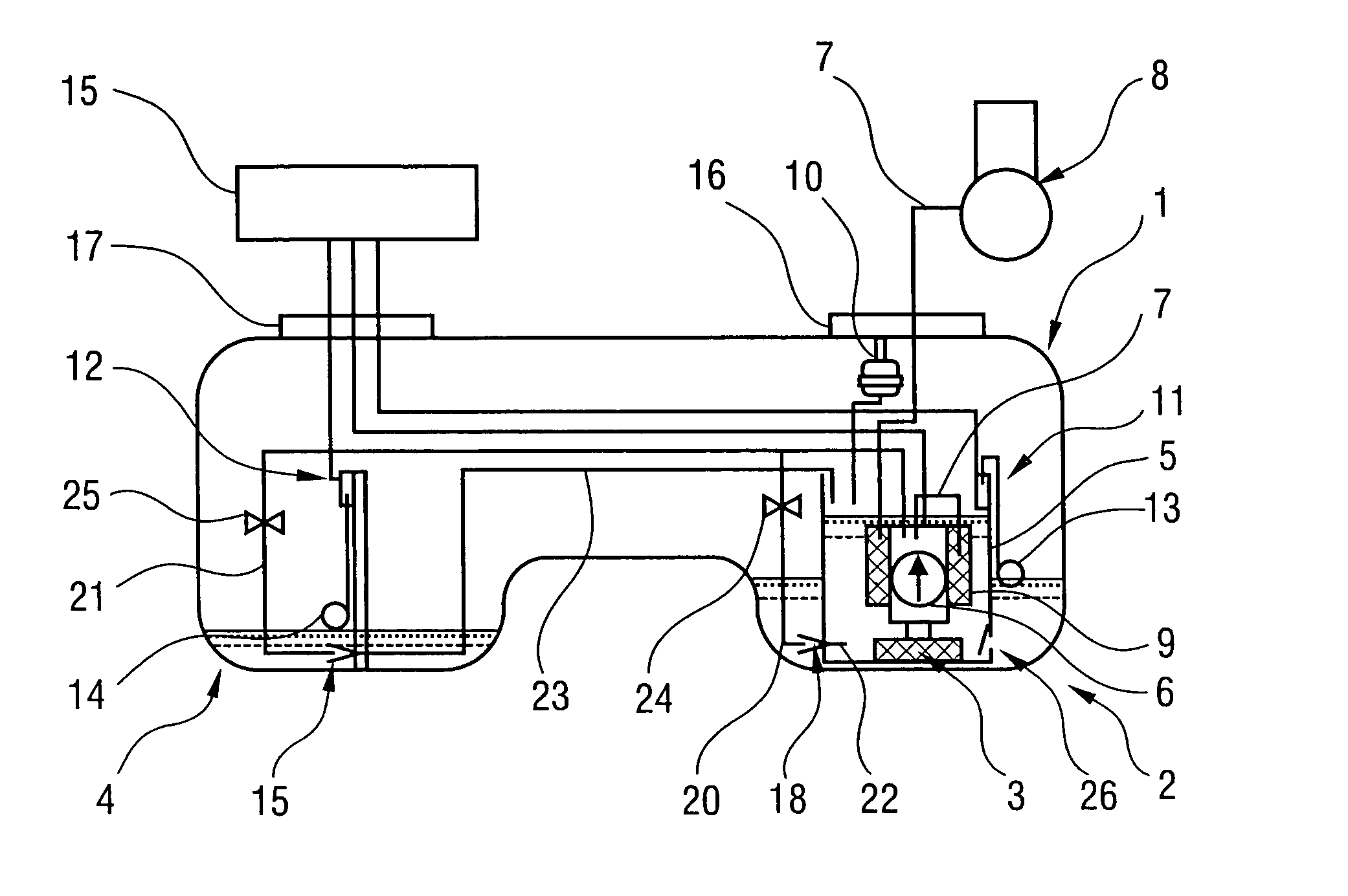
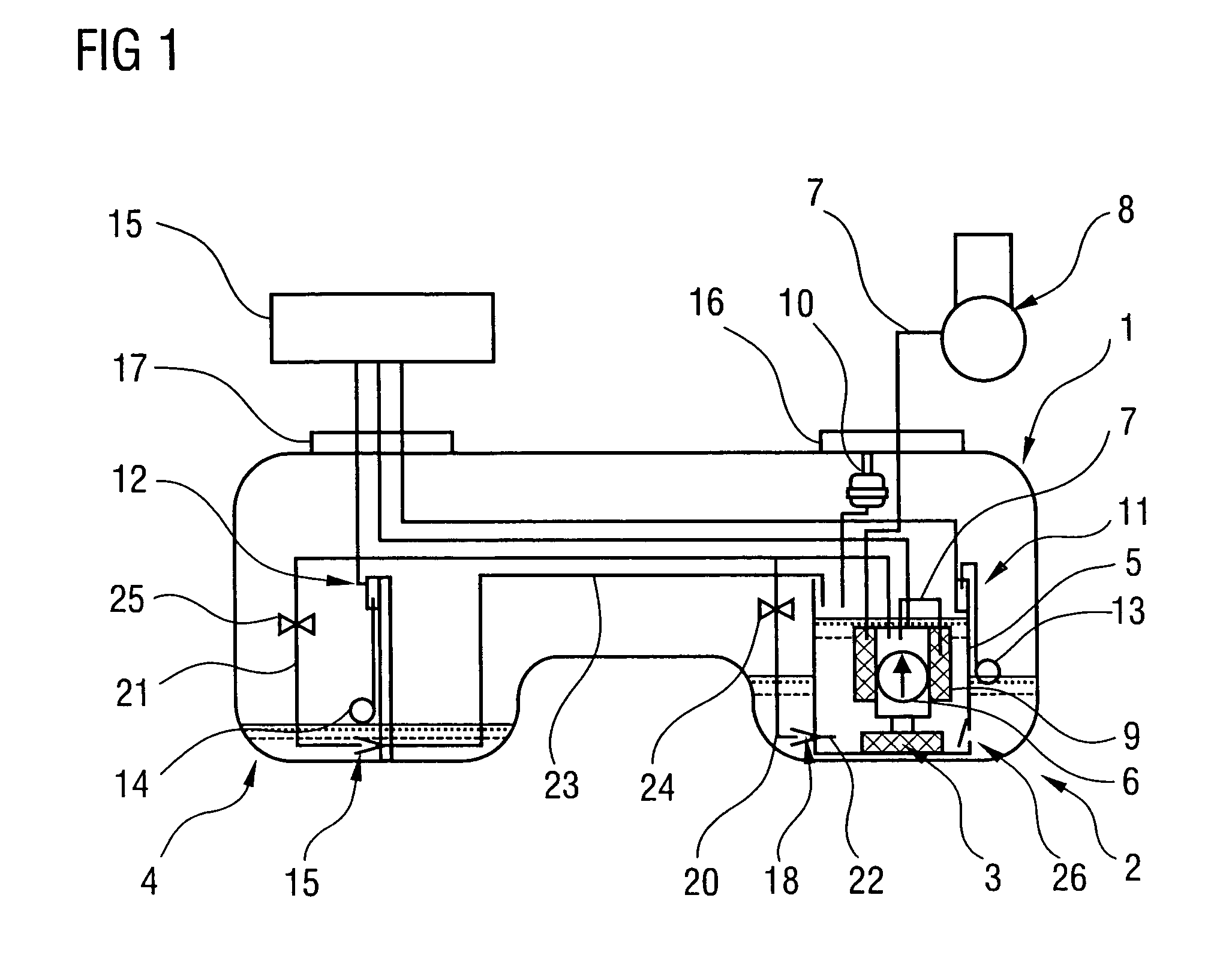
[0022]FIG. 2 is a schematic view of a section through the valve 25—arranged in one of the propellant lines 21—of the fuel container 1 from FIG. 1. The valve 25 has a valve body 27 which closes the suction jet pump 19. The valve body 27 is connected to the float 14 of the filling level sensor 12 via a linkage 28. When there is a low filling level in the chamber 4 which accommodates the suction jet pump 19, the valve body 27 is moved to a position which closes the suction jet pump 19. As a result, fuel is prevented from being fed by the suction jet pump 19 when the chamber 4 is virtually empty.

second embodiment

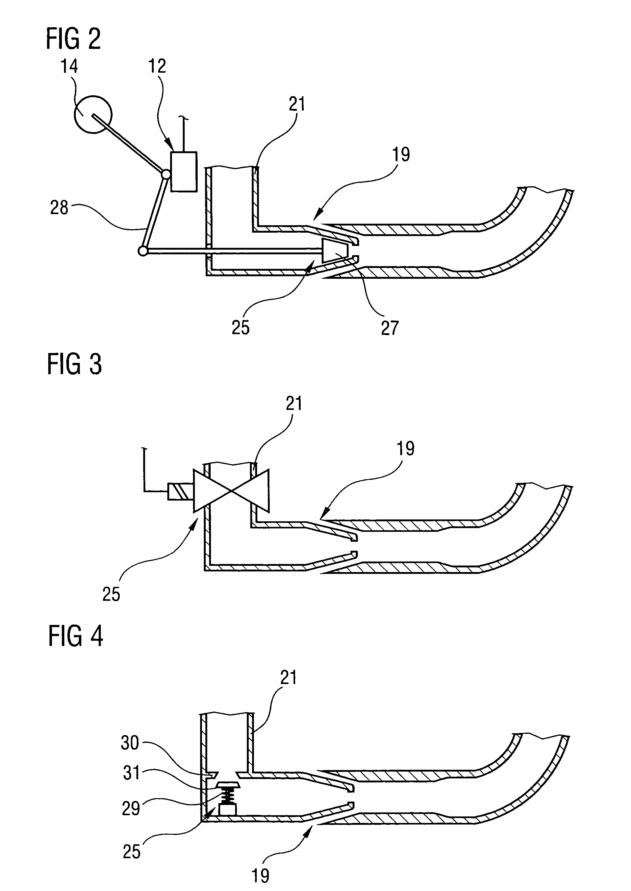
[0023]FIG. 3 is a schematic view of a section through the valve 25 which is arranged in one of the propellant lines 21. The valve 25 can be switched electrically and connected to the control unit 15 from FIG. 1. If the filling level sensor 12 which is arranged in the corresponding chamber 4 from FIG. 1 determines that the chamber 4 is virtually empty, the control unit 15 actuates the valve 25, as a result of which the propellant line 21 is closed. The corresponding suction jet pump 19 thus receives no fuel.

[0024]FIG. 4 is a schematic view of a further embodiment of the valve 25 which is arranged in one of the propellant lines 21. The valve 25 has a closing body 21 which is prestressed against a valve seat 30 by a spring element 29. If it is determined, by the filling level sensors 11, 12, that one or more chambers 2, 4 of the fuel container 1 from FIG. 1 are virtually empty, the control unit 15 reduces the feeding capacity of the fuel pump 6, which brings about a drop in pressure in...


PUM

PropertyMeasurementUnit
pressureaaaaaaaaaa
rotational speedaaaaaaaaaa
permeationaaaaaaaaaa

Abstract

In a fuel container (1) for a motor vehicle having a plurality of chambers (2, 4), a suction jet pump (18, 19) with a filling level sensor (11, 12) is arranged in each of the individual chambers (2, 4). A valve (24, 25) is arranged in a propellant line (20, 21) leading to the suction jet pump (18, 19). When a chamber (2, 4) is virtually empty, the supply of fuel to the suction jet pump (18, 19) is disabled and an unnecessary movement of the fuel is thus avoided.

Description

BACKGROUND OF THE INVENTION[0001]The invention relates to a fuel container for a motor vehicle having a plurality of chambers for collecting fuel, having a fuel feeding unit whose feeding capacity can be regulated, having suction jet pumps which are arranged in at least some of the chambers of the fuel container and have the purpose of feeding fuel to the feeding unit, having a propellant line which leads from the pressure side of the fuel feeding unit to the suction jet pump, having a filling level sensor for acquiring the filling level of fuel, and having a control unit for evaluating the signals of the filling level sensor and for actuating the feeding unit.[0002]Such fuel containers are usually designed as a saddle tank and are known from practice. In this context, the suction jet pumps are used to feed the fuel from the corresponding chamber to the feeding unit or to the chamber holding the feeding unit. The feeding unit frequently has a surge chamber which can be filled by a f...

Claims


Application Information

Patent Timeline
Patent Type & Authority Patents(United States)
IPC IPC(8): B60K15/077F02D33/00F02M37/00F02M37/02F02M37/10
CPCB60K15/077F02M37/0094B60K2015/03105B60K2015/03118B60K2015/03138B60K2015/03144B60K2015/03223F02D33/006F02M37/0023F02M37/0058F02M37/025F02M37/106Y10T137/86075Y10T137/86212
Inventor RUMPF, BERND
Owner CONTINENTAL AUTOMOTIVE GMBH
Why Eureka
Try Eureka