Magnetically operated driving tool
- Summary
- Abstract
- Description
- Claims
- Application Information
AI Technical Summary
Benefits of technology
Problems solved by technology
Method used
Image

Examples
Embodiment Construction
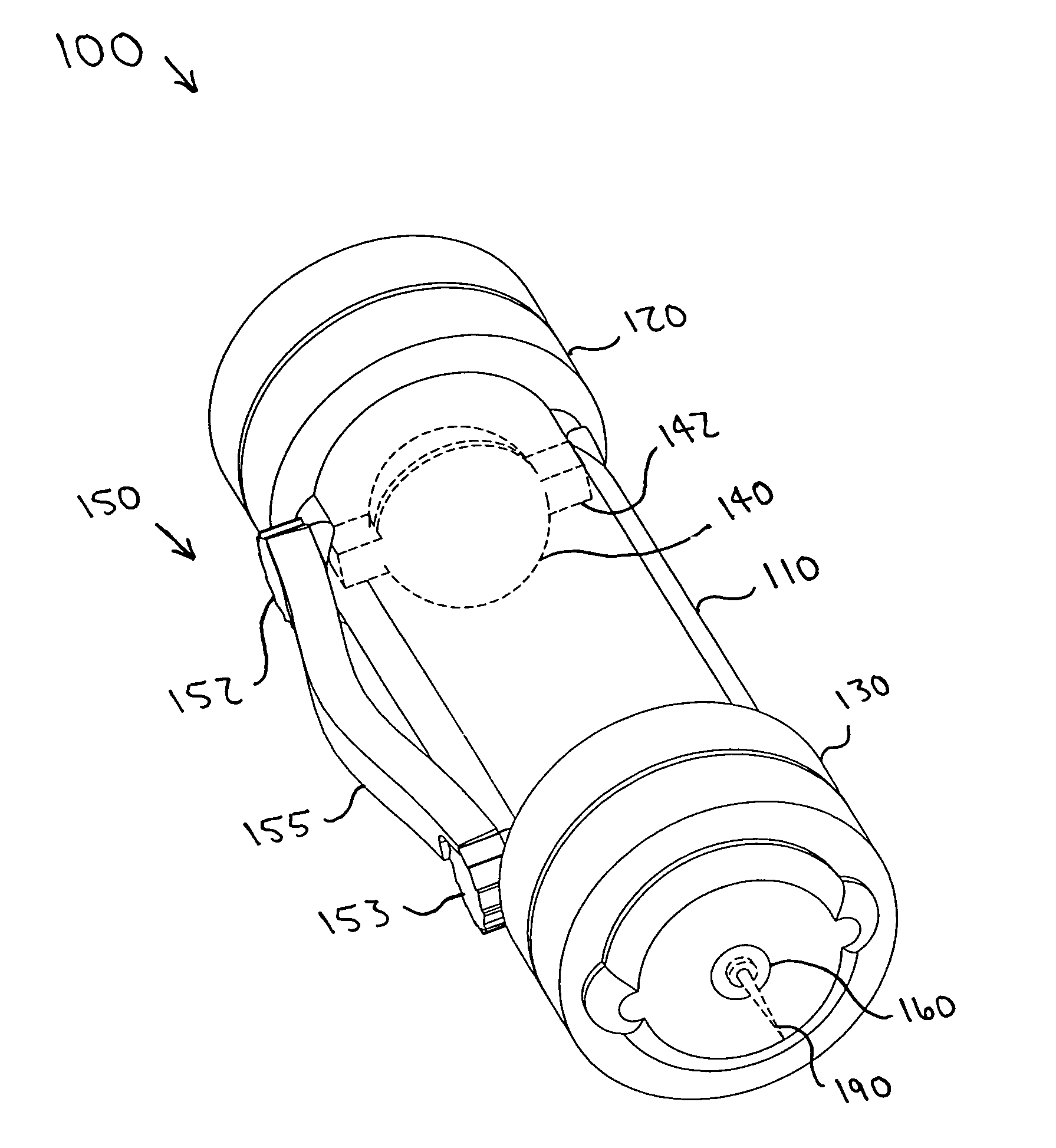
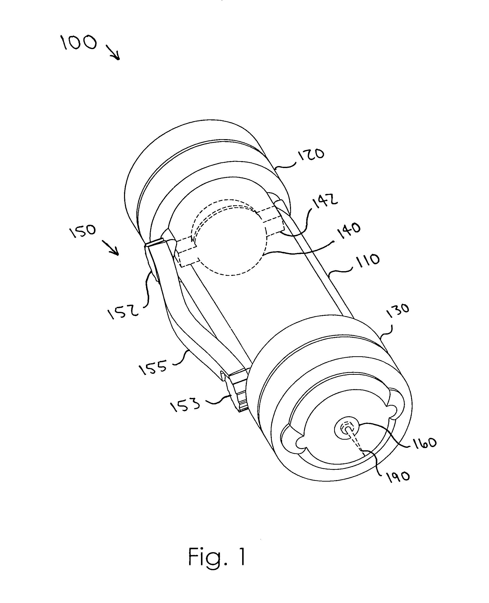
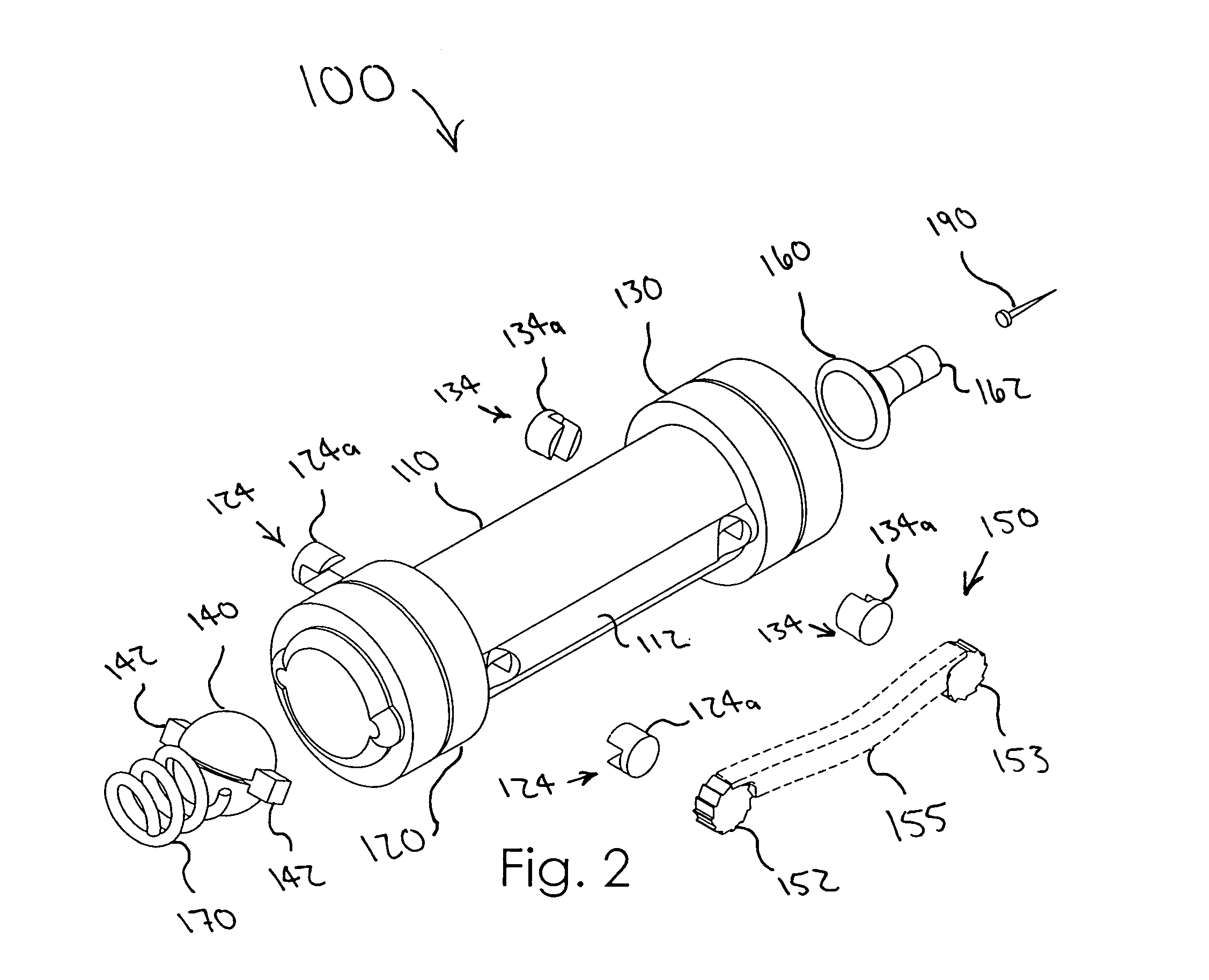
[0023]A magnetically operated driving tool according to the present invention will now be described in detail with reference to FIGS. 1 through 6c of the accompanying drawings. More particularly, a magnetically operated driving tool 100 according to a now preferred embodiment includes a body member 110 having a generally tubular configuration, first and second stationary (stator) magnets 120, 130 mounted in a spaced apart relationship at opposed ends of the body member 110 with like poles facing one another, and a moveable magnet 140 positioned in the body member 110 for magnetically induced movement between the stator magnets 120, 130 (FIGS. 1 and 2). Preferably, the stator magnets 120, 130 have generally ring-shaped configurations such that the movable magnet 140 may pass therethrough for engagement with other components as will be further described later. First and second couplings 124, 134 are positioned in the body member 110 adjacent the first and second stator magnets 120, 13...
PUM
| Property | Measurement | Unit |
|---|---|---|
| Polarity | aaaaa | aaaaa |
| Resilience | aaaaa | aaaaa |
| Magnetic force | aaaaa | aaaaa |
Abstract
Description
Claims
Application Information
 - R&D
- Intellectual Property
- Life Sciences
- Materials
- Tech Scout
- Unparalleled Data Quality
- Higher Quality Content
- 60% Fewer Hallucinations
Browse by: Latest US Patents, China's latest patents, Technical Efficacy Thesaurus, Application Domain, Technology Topic, Popular Technical Reports.
© 2025 PatSnap. All rights reserved.Legal|Privacy policy|Modern Slavery Act Transparency Statement|Sitemap|About US| Contact US: help@patsnap.com