Interleaved clock signal generator having serial delay and ring counter architecture

a clock signal and clock signal technology, applied in the direction of generating/distributing signals, pulse techniques, instruments, etc., can solve the problems of fixed timing offsets and cycle-to-cycle mismatches, received from external sources, and typically caused cycle-to-cycle mismatches, so as to achieve less jitter and small timing errors

a clock signal and clock signal technology, applied in the direction of generating/distributing signals, pulse techniques, instruments, etc., can solve the problems of fixed timing offsets and cycle-to-cycle mismatches, received from external sources, and typically caused cycle-to-cycle mismatches, so as to achieve less jitter and small timing errors

US6956423B2Inactive Publication Date: 2005-10-18KEYSIGHT TECH

Image

  • Interleaved clock signal generator having serial delay and ring counter architecture
  • Interleaved clock signal generator having serial delay and ring counter architecture
  • Interleaved clock signal generator having serial delay and ring counter architecture

Examples


Embodiment Construction

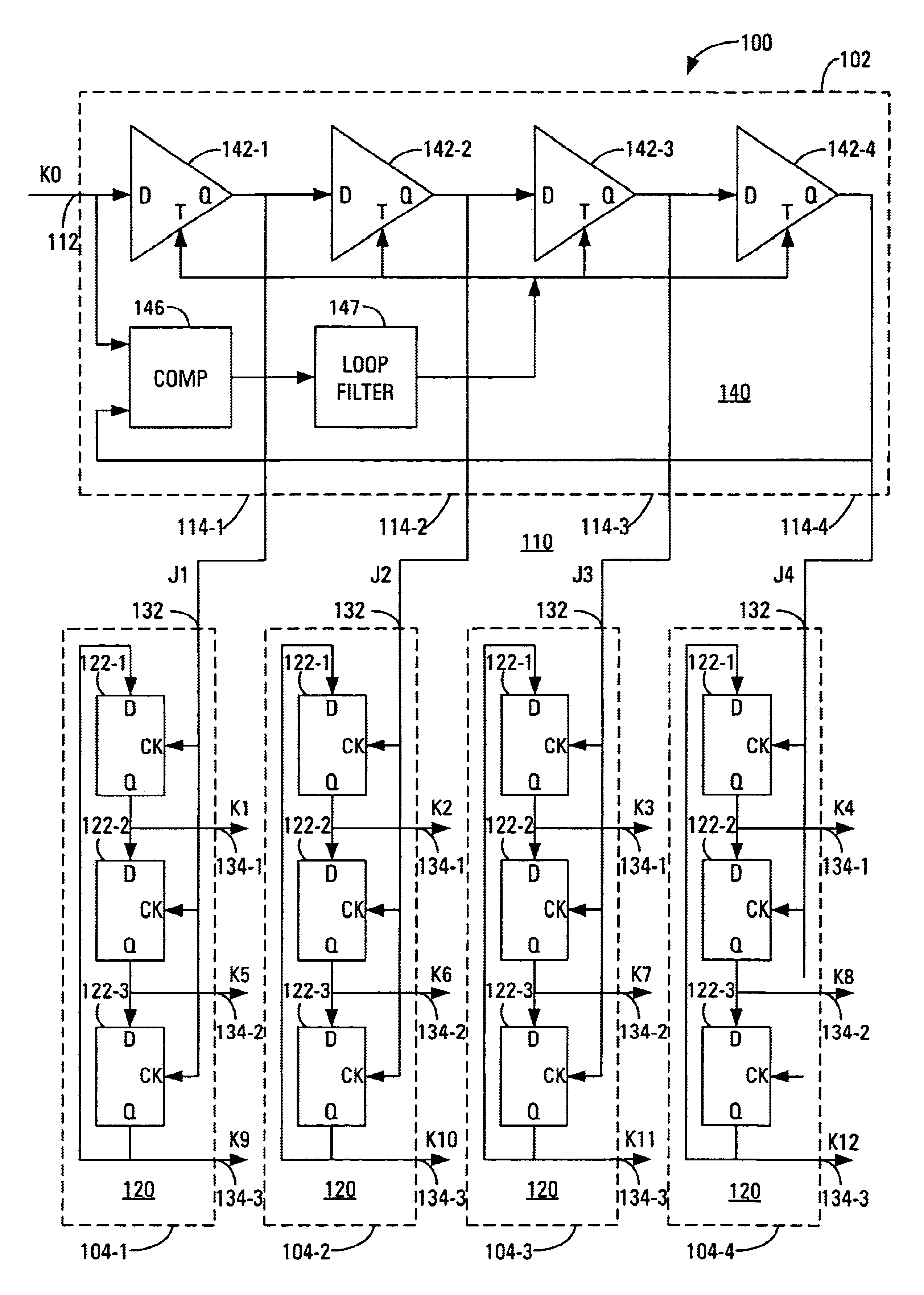
[0049]FIG. 4 is a block diagram of an embodiment 100 of an interleaved clock generator according to the invention. The example shown generates N interleaved clock signals K1-KN in response to the input clock signal K0. Corresponding edges of temporally adjacent ones of the interleaved clock signals differ in time by a time delay Td and the interleaved clock signals have a frequency of 1 / (N×Td).

[0050]The interleaved clock generator 100 is composed of the interleaved clock generator of a first type 102 and the M interleaved clock generators of a second type 104-1, 104-2, . . . , 104-M. The interleaved clock generator of the first type 102 includes the input clock input 112 and the M intermediate clock outputs 114-1, 114-2, . . . , 114-M. The interleaved clock generator of the first type is either a multi-stage serial-delay circuit similar to the multi-stage serial-delay circuit 40 described above with reference to FIG. 3A, or is a ring counter circuit, an example of which is the ring ...


PUM


Abstract

The interleaved clock generator generates N interleaved clock signals in response to an input clock signal. The interleaved clock generator comprises an interleaved clock generator of a first type for receiving the input clock signal and for generating M interleaved intermediate clock signals in response to the input clock signal. The interleaved clock generator of the first type includes either a multi-stage serial-delay circuit or a ring counter circuit. The interleaved clock generator additionally comprises M interleaved clock generators of a second type, each of which is each for receiving a respective one of the intermediate clock signals from the clock generator of the first type and for generating N/M of the N interleaved clock signals in response to the respective one of the intermediate clock signals. Each of the interleaved clock generators of the second type includes either a ring counter circuit or a multi-stage serial-delay circuit: a ring counter when the interleaved clock generator of the first type includes a multi-stage serial-delay circuit; a multi-stage serial-delay circuit when the interleaved clock generator of the first type includes a ring counter circuit.

Description


Claims


Application Information

Patent Timeline
18 Oct 2005
Publication
US6956423B2