Clock generating device and jitter reducing method in the clock generating device

a clock generating device and clock technology, applied in the direction of generating/distributing signals, instruments, transmission monitoring, etc., can solve the problems of increasing the influence of noise on the timing of actual crossing, and the difficulty of generating a clock signal with less jitter

Active Publication Date: 2012-12-25
SEIKO EPSON CORP
View PDF15 Cites 0 Cited by
  • Summary
  • Abstract
  • Description
  • Claims
  • Application Information

AI Technical Summary

Benefits of technology

[0014]An advantage of some aspects of the invention is to generate a clock signal with less jitter.

Problems solved by technology

This makes it difficult to generate a clock signal with less jitter.
This is considered to be because, when the rate of change of the input signal near the crossing with the reference value falls in a comparator, the influence of noise on timing of actual crossing increases.

Method used


Image

  • Clock generating device and jitter reducing method in the clock generating device
  • Clock generating device and jitter reducing method in the clock generating device
  • Clock generating device and jitter reducing method in the clock generating device

Examples


application example

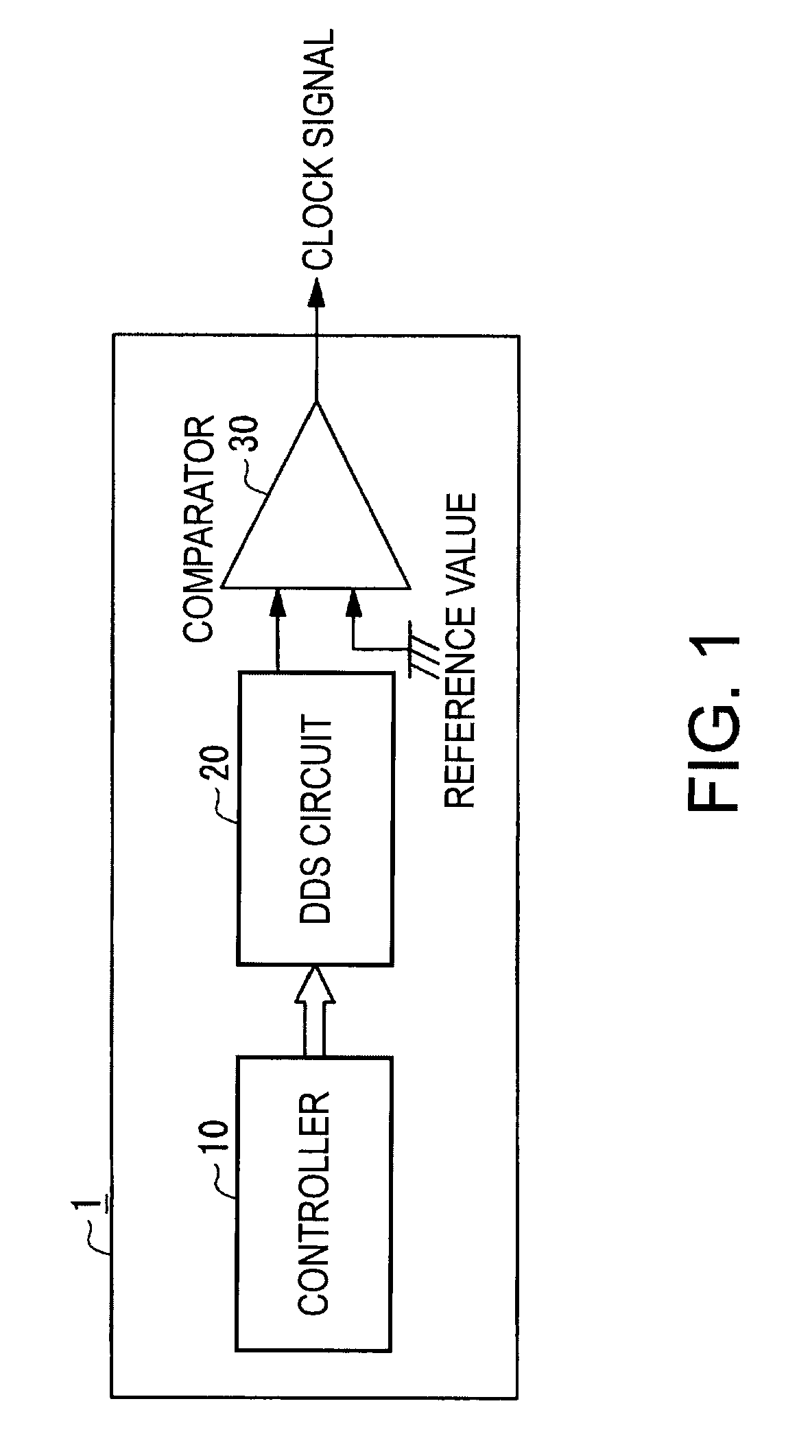
[0076]In the embodiment explained above, the controller 10 only has to simply output a constant value to the DDS circuit 20. However, it is possible to perform clock generation for setting a clock frequency to be generated variable by setting an output value of the controller 10 variable.

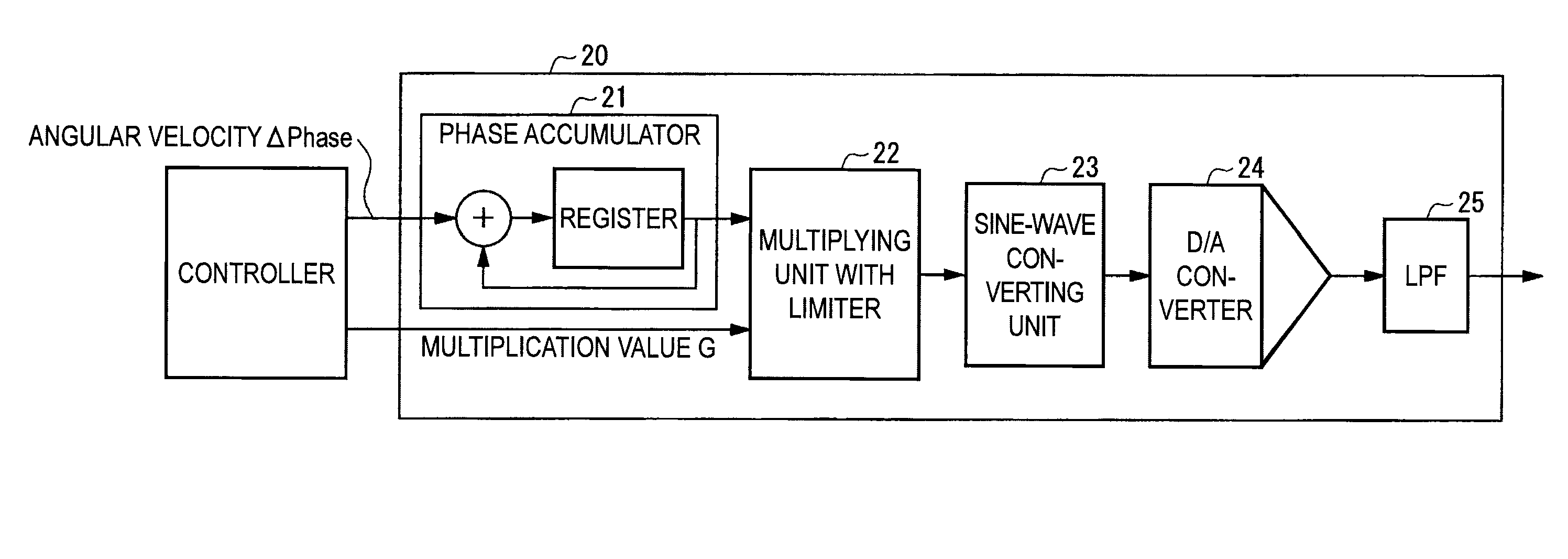
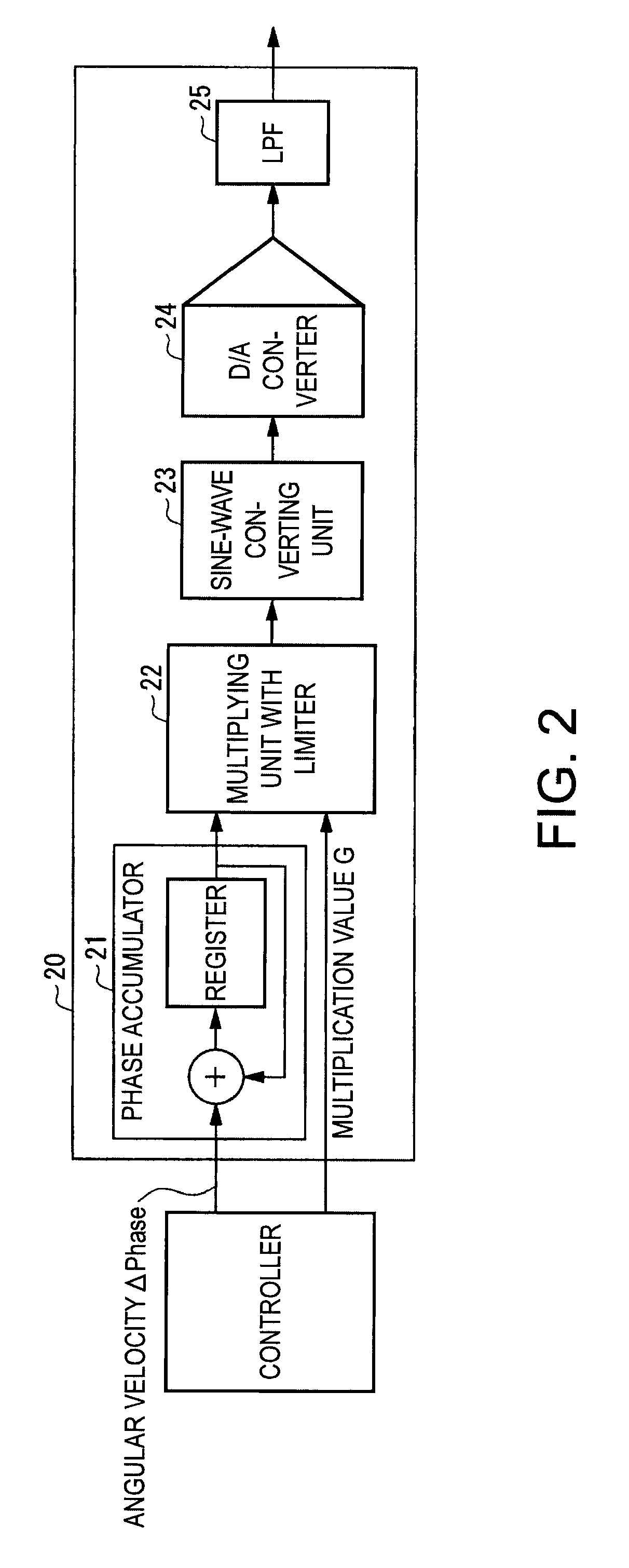
[0077]When a generated frequency is set high, since a rate of change is large from the beginning, it is unnecessary to increase the rate of change. Moreover, the number of samples of the phase θ before and after a crossing point is small because a generated clock cycle is short. If the rate of change is increased, the number of samples further decreases and jitter is deteriorated to the contrary. Therefore, the multiplication value G is set to 1 not to perform correction of the rate of change in a frequency range equal to or higher than a certain degree.

[0078]When the generated frequency is set low, the multiplication value G is set large according to a degree of setting the generated frequency low....


PUM


Abstract

A clock generating device includes: a DDS circuit that generates a periodic signal; and a comparator that compares an input signal and a reference signal and outputs a binary signal. The clock generating device includes a rate-of-change correcting unit that applies correction for increasing a rate of change at a crossing point with the reference signal to the periodic signal generated by the DDS circuit.

Description

BACKGROUND[0001]1. Technical Field[0002]The present invention relates to a clock generating device that generates a clock signal and a jitter reducing method in the clock generating device.[0003]2. Related Art[0004]In the past, there is known a clock generating device employing a DDS (Direct Digital Synthesizer) circuit that generates a periodic signal.[0005]In the clock generating device employing the DDS circuit, in the DDS circuit, a phase accumulator that adds up phases by a value Δphase, which determines angular velocity of a generation frequency, at a time sequentially accumulates and adds up Δphase and, as a result of the accumulation and addition, sequentially outputs, as a digital value, a phase θ for generating angular velocity of a predetermined periodic signal.[0006]The amplitude of a sine wave is acquired as a digital value by a sine-wave converting unit that converts the phase θ into the amplitude of the sine wave.[0007]The amplitude of the sine wave output in this way...

Claims


Application Information

Patent Timeline
Patent Type & Authority Patents(United States)
IPC IPC(8): H03B21/00
CPCG06F1/025G06F1/08
Inventor YAMADA, HIDEAKI
Owner SEIKO EPSON CORP
Why Eureka
Try Eureka