Optical pickup

a technology of optical pickups and pickups, applied in the field of optical pickups, can solve the problems of a lot of jitters in recorded/reproduced signals or tracking errors, out-of-focus recording/reproduction with a lot of jitters in recorded/reproduced signals, etc., and achieve the effects of low jitter, low sensitivity, and constant recording/reproduction performan

Active Publication Date: 2011-12-06
JVC KENWOOD CORP
View PDF1 Cites 0 Cited by
  • Summary
  • Abstract
  • Description
  • Claims
  • Application Information

AI Technical Summary

Benefits of technology

[0039]A purpose of the present invention is to provide an optical pickup that exhibits constant recording / reproduction performance at high focus sensitivity, with few jitters to focus-error detection signals, irrespective of the positional accuracy of optical components in optical pickup assembly.

Problems solved by technology

Discussed below with reference to FIGS. 1 to 3 are problems that occur: when a known optical pickup having a hologram element in accordance with the astigmatism method is provided with two types of laser source; and when such a known optical pickup is used for reproduction of an optical disc having two information recording layers.
Discussed below first is a problem related to the two types of laser source used in the known optical pickup 100.
Such lower focus-servo error detection sensitivity could cause delay in tracking of a fluctuating optical disc by the objective lens 104 in recording / reproduction in FIG. 1, which causes a lot of jitters in recorded / reproduced signals or tracking errors.
This results in noises being added to a focus-error detection signal in the photo receptor 105, which causes out-of-focus recording / reproduction with a lot of jitters in recorded / reproduced signals.

Method used


Image

  • Optical pickup
  • Optical pickup
  • Optical pickup

Examples


Embodiment Construction

[0050]A preferred embodiment and modification of an optical pickup according to the present invention will be described with reference to FIGS. 4 to 9.

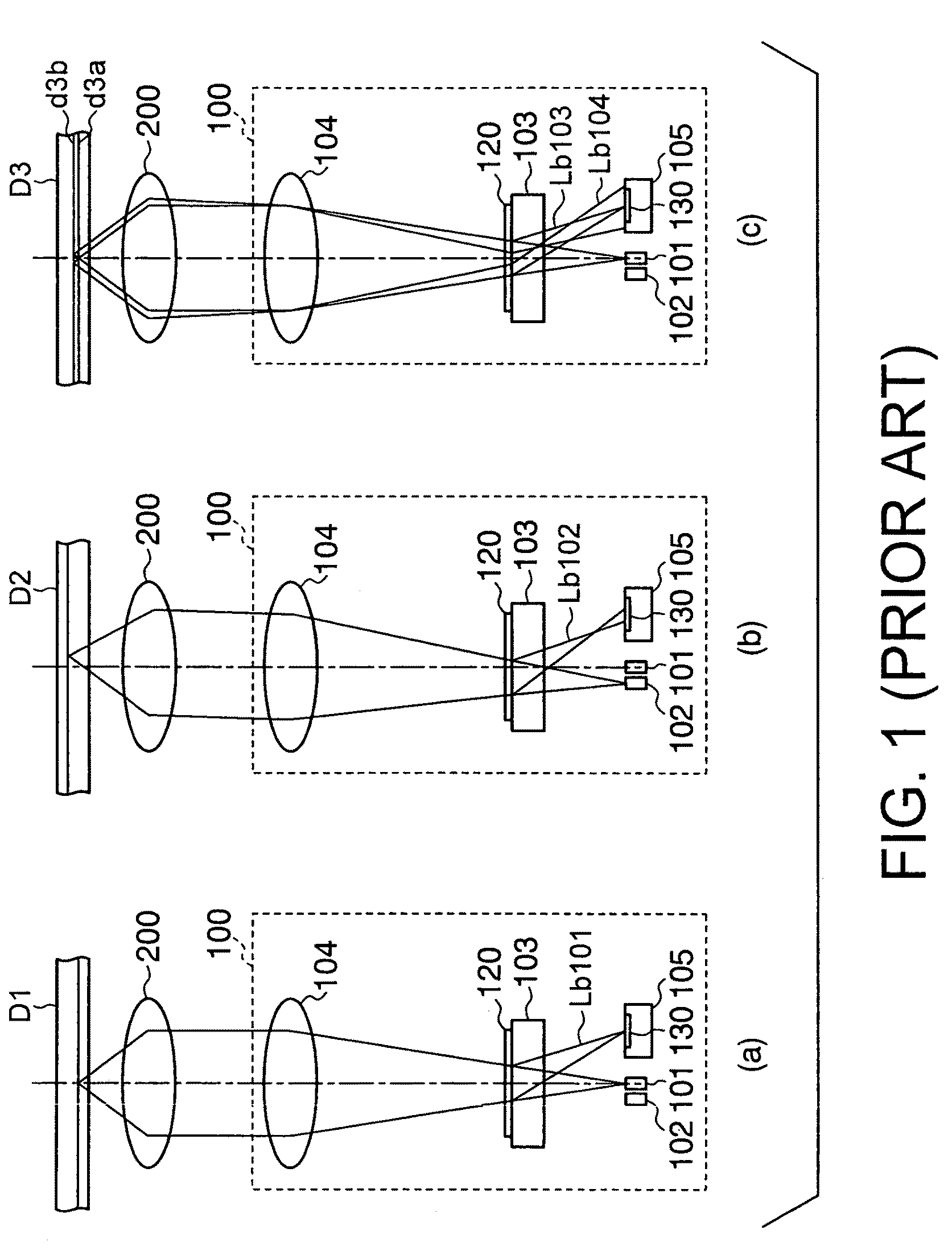
[0051]FIG. 4 shows schematic illustration of a positional relationship between an optical pickup, an embodiment according to the present invention, and an objective lens and an optical disc. In detail, (a), (b) and (c) of FIG. 4 are sectional views illustrating reproduction of a DVD, a CD, and, a dual-layered DVD, respectively, corresponding to (a), (b) and (c) of FIG. 1, respectively.

[0052]FIG. 5 is a plan view of a hologram section of the optical pickup, the embodiment according to the present invention.

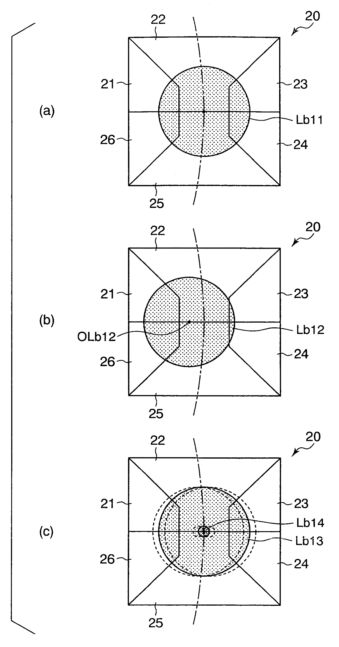
[0053]FIG. 6 shows schematic illustration of a hologram section in the optical pickup, the embodiment according to the present invention. In detail, (a), (b), and (c) of FIG. 6 are plan views illustrating a beam on the hologram section, returned from a DVD, a CD, and a dual-layered DVD, respectively, in reproduction, corresponding to...


PUM

PropertyMeasurementUnit
distanceaaaaaaaaaa
distanceaaaaaaaaaa
distanceaaaaaaaaaa

Abstract

An optical-pickup hologram element has six regions on an x-y plane, divided as follows: the first region with a first line (an x-axis) and a second line that connects points (−xa, 0) and (−xb, yb); the second region with the first and second lines and a third line connecting points (xa, 0) and (xb, yb); the third region with the first and third lines; the fourth region with the first line and a fourth line connecting the point (xa, 0) and a point (xb, −yb); the fifth region with the first and fourth lines and a fifth line connecting the point (−xa, 0) and a point (−xb, −yb); and the sixth region with the first and fifth lines (xa<xb and −xb<−xa). The second and fifth, and the other regions are given astigmatism at different angles to the second line.

Description

CROSS-REFERENCE TO RELATED APPLICATIONS[0001]This application is based on and claims the benefit of priority from the prior Japanese Patent Application No. 2009-104877 filed on Apr. 23, 2009, the entire contents of which is incorporated herein by reference.BACKGROUND OF THE INVENTION[0002]The present invention relates to an optical pickup for recording / reproducing information on / from an optical disc, especially, provided with a hologram element.[0003]A known optical pickup is provided with a hologram element in accordance with an astigmatism method, aiming for both of focus error detection and compactness as well as high reliability.[0004]Another known optical pickup is provided with two laser sources with different wavelengths for two types of optical disc with different recording densities, such as, CD and DVD. This type of optical disc is generally provided with a laser source dedicated for DVD that is an optical disc of high recording density used at shorter wavelength than CD a...

Claims


Application Information

Patent Timeline
Patent Type & Authority Patents(United States)
IPC IPC(8): G11B7/00
CPCG11B7/1353G11B7/13922G02B5/32
Inventor KANEKO, TAKAHIROHIRAGA, TAKAYOSHI
Owner JVC KENWOOD CORP
Why Eureka
Try Eureka