Method and apparatus for controlling a massively parallel processing environment

a massively parallel processing and environment technology, applied in the direction of instruments, general purpose stored program computers, cad circuit designs, etc., can solve the problems of large number of fpga chips required for complex designs, large number of fpga chips required for reconfiguring the fpga arrangement, and limited number of pins that each processor has

Active Publication Date: 2005-10-18
ORACLE INT CORP
View PDF9 Cites 8 Cited by
  • Summary
  • Abstract
  • Description
  • Claims
  • Application Information

AI Technical Summary

Benefits of technology

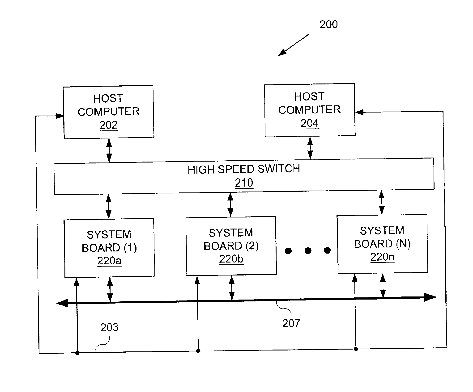
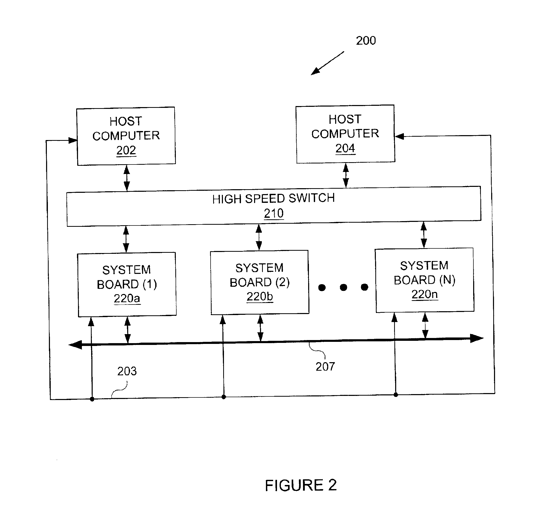
[0014]In general, in one aspect, the present invention involves a host computer system for controlling a processor array. The host computer system comprises a processor, a memory, a storage device, and software instructions stored in the memory for enabling the host computer system under the control of the processor, to perform creating a graph of a plurality of nodes using a data connection component, configuring a broadcast tree from a spanning tree...

Problems solved by technology

As the design changes, the time required to reconfigure the FPGA arrangement may prohibit many iterations.
Also, the number of FPGA chips required for complex designs may be relatively large.
The number of pins that each processor has, howe...

Method used


Image

  • Method and apparatus for controlling a massively parallel processing environment
  • Method and apparatus for controlling a massively parallel processing environment
  • Method and apparatus for controlling a massively parallel processing environment

Examples


Embodiment Construction

[0029]Specific embodiments of the invention will now be described in detail with reference to the accompanying figures. Like elements in the various figures are denoted by like reference numerals for consistency.

[0030]The present invention is a method and apparatus for controlling a massively parallel processing environment. In the following detailed description of the invention, numerous specific details are set forth in order to provide a more thorough understanding of the invention. However, it will be apparent to one of ordinary skill in the art that the invention may be practiced without these specific details. In other instances, well-known features have not been described in detail to avoid obscuring the invention.

[0031]In an embodiment of the present invention, the computer execution environment may use execution processors to execute execution processor code on a general purpose computer, such as a SPARC™ workstation produced by Sun Microsystems, Inc., or specialized hardwa...


PUM


Abstract

A method for controlling a processor array by a host computer involves creating a graph of a plurality of nodes using a data connection component, configuring a broadcast tree from a spanning tree of the graph, propagating a first command from the host computer to a member of the processor array using the broadcast tree, configuring a reply tree from a spanning tree of the graph, transmitting a response from the member of the processor array to the host computer using the reply tree, and configuring the data connection component to send at least one message selected from the first command and the response on at least one run mode communication path.

Description

[0001]This application claims benefit to Provisional Application Ser. No. 60 / 313,217, filed Aug. 17, 2001, entitled “Phaser System Architecture,” and invented by Thomas M. McWilliams; Jeffrey B. Rubin; Derek Pappas; Kunle Olukotun; Jeffrey Broughton; David R. Emberson; William Lam; Liang T. Chen; Ihao Chen; Earl T. Cohen; and Michael Parkin.BACKGROUND OF THE INVENTION[0002]Cycle-based logic simulation is applicable to synchronous digital systems and may be utilized to verify the functional correctness of a digital design. Cycle-based simulators use algorithms that eliminate unnecessary calculations to achieve improved performance in verifying system functionality. Typically, in a cycle-based logic simulator the entire system is evaluated once at the end of each clock cycle. Discrete component evaluations and re-evaluations are typically unnecessary upon the occurrence of every event.[0003]HDL simulations may be event driven or cycle-based. Event driven simulations propagate a change...

Claims


Application Information

Patent Timeline
IPC IPC(8): G06F17/50
CPCG06F17/5022G06F30/33
Inventor EMBERSON, DAVID R.BROUGHTON, JEFFREY M.BURR, JAMES B.PAPPAS, DEREK E.
Owner ORACLE INT CORP
Why Eureka
Try Eureka