Envelope-filling station for mail processing systems

a mail processing system and envelope filling technology, applied in the field of envelope filling stations for mail processing systems, to achieve the effect of facilitating the transfer of documents, and high working speed

Inactive Publication Date: 2005-10-25
DMT SOLUTIONS GLOBAL CORP +1
View PDF12 Cites 13 Cited by
  • Summary
  • Abstract
  • Description
  • Claims
  • Application Information

AI Technical Summary

Benefits of technology

[0009]However, in the envelope-filling station disclosed here, the pressure-exerting roller that interacts with the top strand of the intermittently driven conveying belt of the envelope-advancing arrangement and is pre-stressed in a downward direction performs a stop function independently of the cyclical control of the coupling means that interact with the upper stand of the conveying belt of the envelope-advancing arrangement, in particular independently of the upward and downward movements of the roller bar, and said stop function does not require a separate control means, which reduces the entire expense required for control.

Problems solved by technology

This can lead to problems when envelopes are filled with a relatively heavy content and when there are unfavorable friction ratios between the upper surface of the envelope-filling table and the lower side of the filled envelope.
Moreover, with the prior-art envelope-filling station it can become difficult in the area of the angled intermediate envelope-conveying arrangement to arrange the conveying belts, which extend at an angle relative to the conveying direction of the envelope-feeding arrangement, and thus the hold-down means that work together with said belts and are embodied as rollers or rolling bodies held in cages, on the envelope-filling table in such a way that an envelope that is to be filled reaches the area in front of the inserting station in complete form, and at the same time remains accessible from above on its path, for example to correct problems.

Method used


Image

  • Envelope-filling station for mail processing systems
  • Envelope-filling station for mail processing systems

Examples


Embodiment Construction

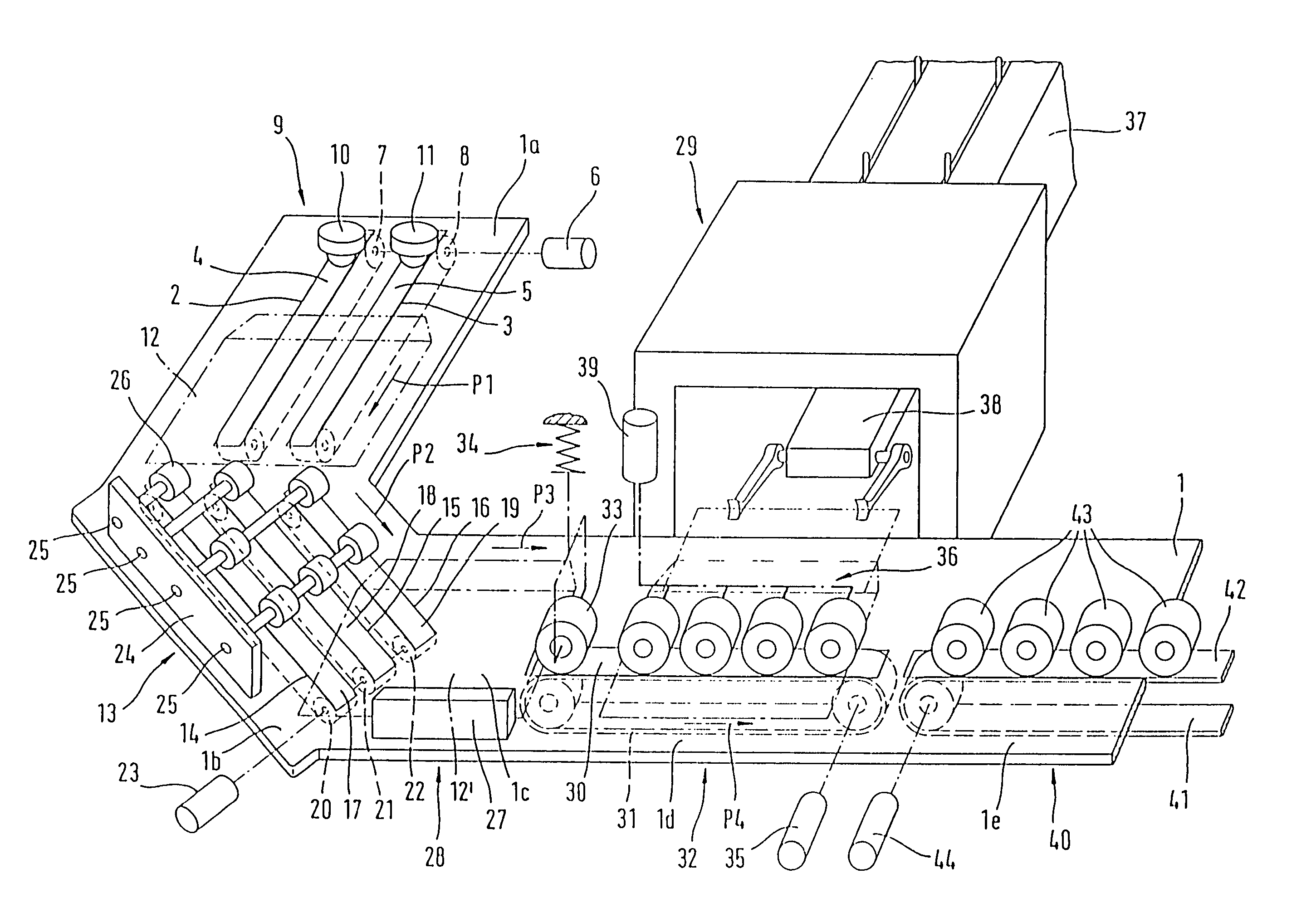
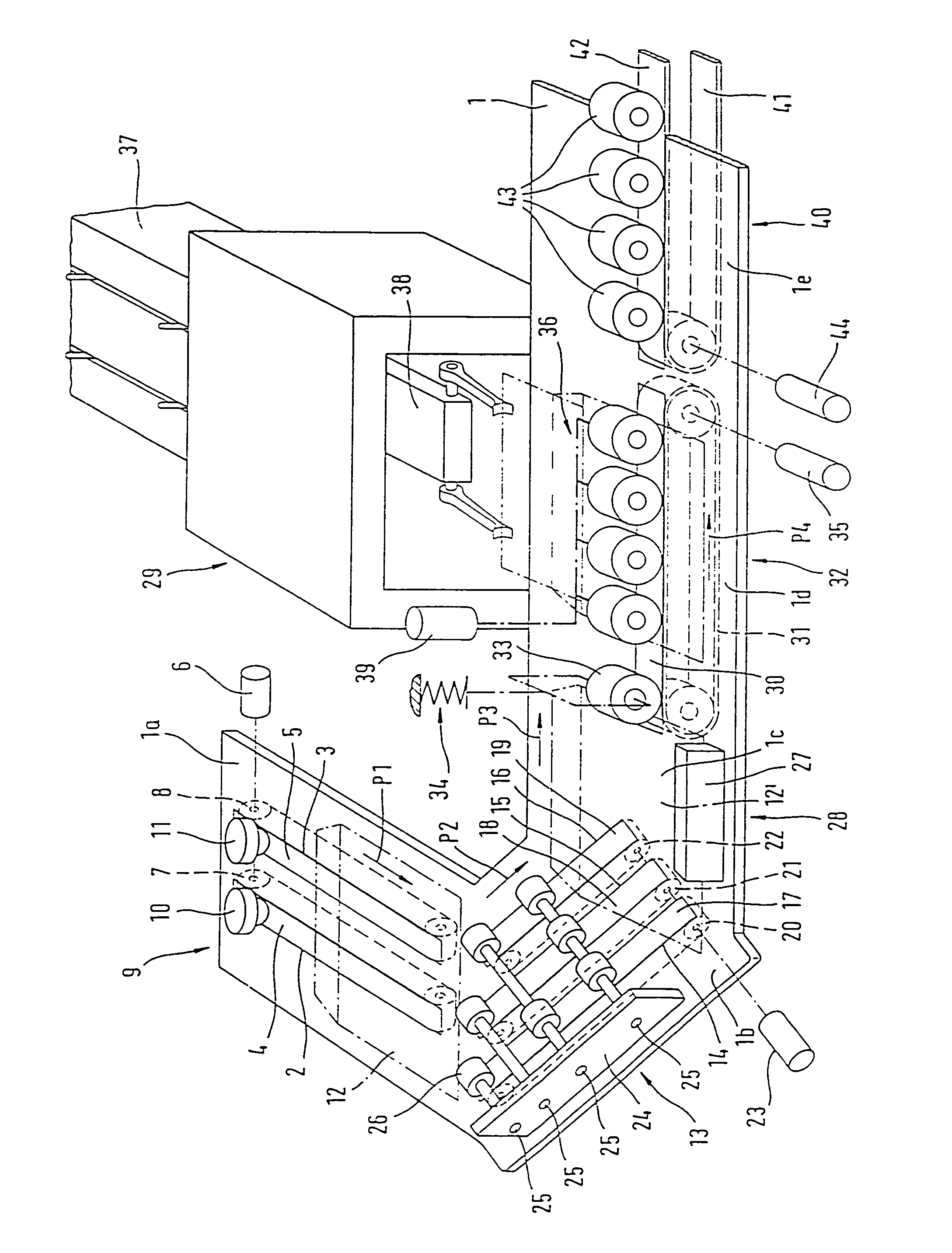
[0012]The drawing shows an L-shaped section of an envelope-filling table 1, which is drawn as a single piece in order to define the working plane of the envelope-filling station. However, in actual embodiments sections of envelope-conveying tables or envelope-filling tables that can be moved relative to each other are provided in a manner that corresponds to the requirements of the individual system components.

[0013]The upper strands 4 and 5 of a continuous conveying belt or conveying belts 7 and 8 of an envelope-feeding arrangement 9 that can be placed in motion by a drive 6 extend through the slots 2 and 3 of an envelope-filling table section 1a. The upper strands 4 and 5 of the conveying belts 7 and 8 work together with hold-down means in the form of roller bearings 10 and 11 guided in cages. Rows of such rolling bodies may be provided along the length of the conveying belts.

[0014]The envelope-feeding arrangement 9 delivers a stream of single, open envelopes in an essentially hor...


PUM


Abstract

In an envelope-filling station for mail processing systems having an envelope-feeding arrangement for single, open envelopes, an intermediate envelope-conveying arrangement extending at an angle thereto in the direction of an angle stop arrangement provided for the purpose of aligning the envelope, and an envelope-advancing arrangement from which the envelopes are accepted from the angle stop arrangement, a simplification of the design, and effort needed to control the component parts is achieved when the angle stop arrangement, with the exception of a stopping straightedge that is to be provided to achieve extremely precise alignment of an envelope that is supplied at an angle, contains as a further part of the angle stop arrangement a conveying nip between the upper strand of an intermittently driven conveying belt of the envelope-advancing arrangement and a pressure-exerting roller that is pre-tensioned near the beginning of the upper strand of this conveying belt. The envelope-advancing arrangement has coupling means following the pressure-exerting roller that interact with the intermittently driven upper strand of the conveying belt of this envelope-advancing arrangement, in particular a roller bar that can be moved up and down, said means conveying an aligned envelope to a position in front of the feeding station, independent of the function of the pressure-exerting roller, and transporting the filled envelope out of the inserting station.

Description

BACKGROUND OF THE INVENTION[0001]The invention relates to an envelope-filling station for mail processing systems.[0002]An envelope-filling station of this type is disclosed in German patent 10220908 C1. It contains an envelope-conveying device having an envelope-feeding arrangement that extends works essentially in the horizontal plane, approximately in the horizontal plane of the surface of an envelope-filling table, an envelope-conveying arrangement which follows this intermediate envelope-conveying arrangement extending at an angle relative to the conveying direction of the envelope-feeding arrangement, and a following envelope-advancing arrangement, whose conveying direction is horizontally perpendicular to the conveying direction of the envelope-feeding arrangement and is perpendicular to the inserting direction of an intermediate envelope-conveying arrangement that is located next to the enclosure-inserting station.[0003]In the disclosed envelope-filling station, the intermed...

Claims


Application Information

Patent Timeline
Patent Type & Authority Patents(United States)
IPC IPC(8): B43M3/00B43M3/04
CPCB43M3/045
Inventor BOTSCHEK, CHRISTIANSTING, MARTIN
Owner DMT SOLUTIONS GLOBAL CORP
Why Eureka
Try Eureka