Mechanical release or trigger device

a trigger device and mechanical technology, applied in the direction of firing/trigger mechanism, compressed gas guns, white arms/cold weapons, etc., can solve the problems of affecting shot accuracy, unusable movement or force of bowstrings, and finger not being able to pull the trigger straight back

Inactive Publication Date: 2005-10-25
NEW ARCHERY PRODS
View PDF21 Cites 19 Cited by
  • Summary
  • Abstract
  • Description
  • Claims
  • Application Information

AI Technical Summary

Benefits of technology

[0011]One object of this invention is to provide a mechanical release or trigger device having a rolling sleeve or other similar mechanical element that is rotatably mounted with respect to a shaft of the trigger. As the trigger shaft moves or pivots with respect to the trigger body, a user's finger contacts the rolling sleeve which freely rotates about the trigger shaft and / or moves along the trigger shaft in at least one direction with respect to an axis of the trigger shaft. The rotational movement of the rolling sleeve about the trigger shaft and / or the axial movement of the rolling sleeve along the trigger shaft reduces a pulling force that, as discussed with respect to the prior art, would otherwise misalign the trigger body with respect to the bowstring when pulling the trigger in the firing or pivot direction.
[0013]The mechanical release or trigger device also includes a sleeve rotatably connected to the trigger. Preferably, the sleeve is positioned about at least a portion of the shaft. In one embodiment, the sleeve is movable along at least a portion of a length of the shaft and rotatable about the shaft with respect to the shaft axis. The sleeve may be one continuous piece or may be segmented, including a plurality of sleeve pieces each rotatable about and movable along the shaft with respect to the shaft axis. The sleeve may have a cylindrical outer surface or an asymmetric, an arcuate or a curved outer surface. For example, at least a portion of the sleeve may form a flange or lip surface. At least a portion of the sleeve outer surface may be knurled or otherwise roughened to provide frictional interference to prevent slippage of a user's finger as the user applies a force to the trigger to move or pivot the trigger between a first position and a second position. At least a portion of the sleeve outer surface can be made of a soft, conformable and / or resilient material to provide user comfort, reduce shock and increase firing accuracy.
[0018]In one preferred embodiment of this invention, the mechanical release or trigger device is used in combination with a firearm having a two-stage trigger. A two-stage trigger typically has three trigger positions, with a starting position, an intermediate position and an activating position. Movement from the first or starting position to the intermediate position generally requires a greater amount of force than movement from the intermediate position to the third or activating position. The two-stage trigger is considered to aid in target shooting accuracy. It should be apparent to those having ordinary skill in the art that the mechanical release or trigger device of the present invention is functionable with a trigger having any number of trigger positions.

Problems solved by technology

Such pulling movement of the trigger typically results in an undesirable movement of or force on the bowstring in a vertical, horizontal and / or forward / rearward vector or direction.
A trigger pull that is not in line or parallel with the arrow negatively influences shot accuracy.
However, a finger cannot pull the trigger straight back because of its pivotal or hinged connection to the user's hand.
This pulling movement can result in undesired movement of or force on the trigger device in a vertical, horizontal and / or forward / rearward vector or direction, which negatively influences shot accuracy.
With conventional trigger devices, as a user's finger is applied to pull or force a trigger in a pivot direction, because of friction between the user's finger and the trigger, a trigger body moves with respect to a bowstring and causes an undesired misalignment of the trigger body with respect to the bowstring.
Force components F2 and F3 acting on the bowstring will apply an undesired force on the bowstring, misalign the arrowshaft with respect to a target, and result in an inaccurate arrow launch.
However, similar problems result because a user's fingers will not move precisely or synchronously with the movement of the mechanical linkages.
Therefore, undesirable resultant movement or force may be present in these conventional moving triggers as well.
Similar problems are associated with conventional firearm triggers that move or pivot to activate a release aid to fire a projectile for example.
The frictional forces between the finger and the trigger produce an undesirable resultant movement or force that results in misalignment of the firearm barrel with respect to a target.

Method used


Image

  • Mechanical release or trigger device
  • Mechanical release or trigger device
  • Mechanical release or trigger device

Examples


Embodiment Construction

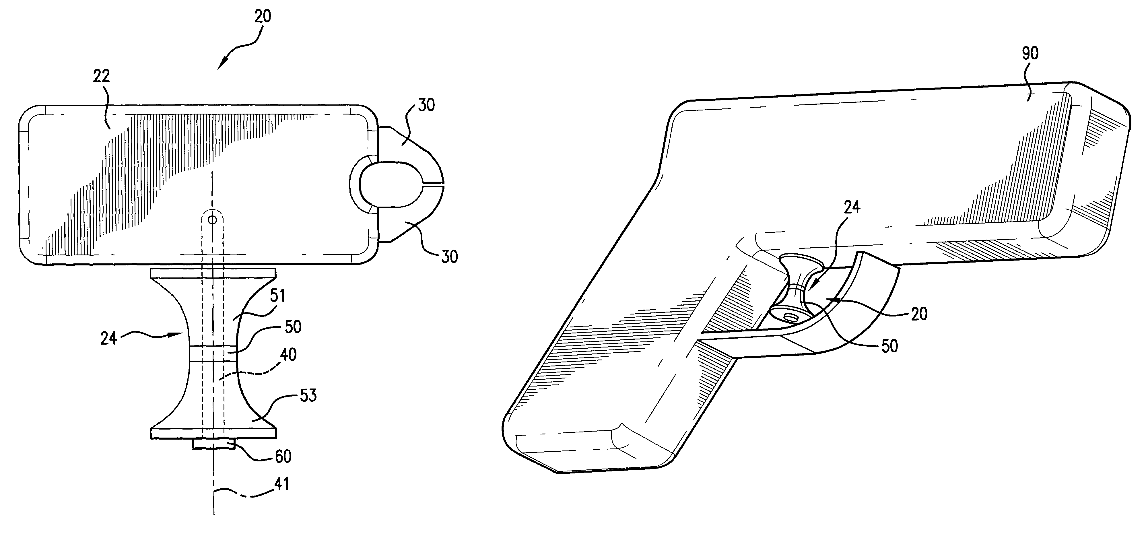
[0030]This invention is directed to a mechanical release or trigger device for activating a trigger mechanism. Although the various aspects and embodiments of this invention are described in the context of a mechanical release or trigger device for use in combination with an archery bow for drawing an archery bowstring and moving or pivoting a trigger to activate a release mechanism to launch an arrow, the mechanical release or trigger device of this invention can be used in combination with a firearm, such as a gun, to launch or project any suitable projectile from a launching device, by moving or pivoting a trigger to activate a release mechanism.

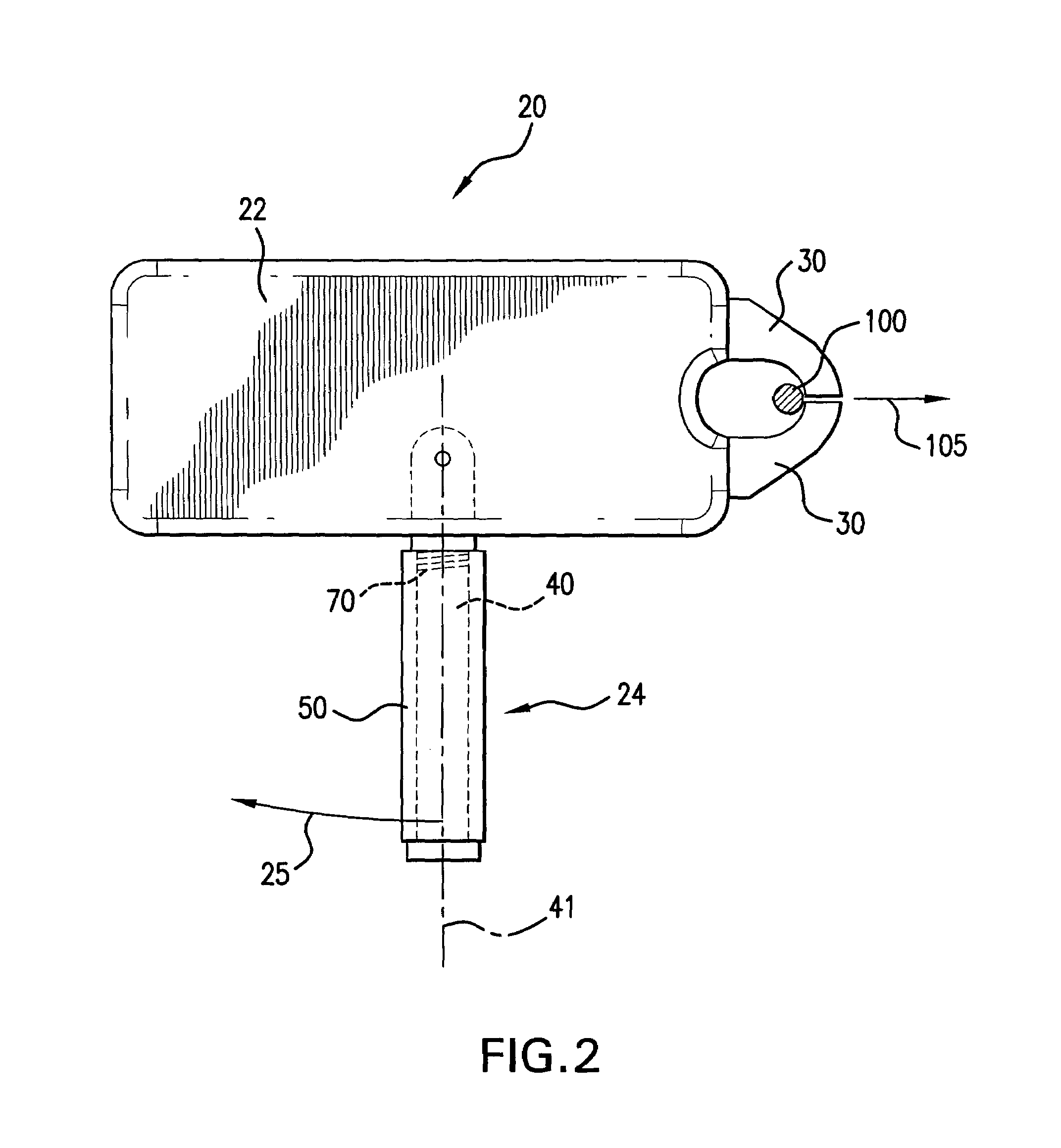
[0031]In one preferred embodiment of this invention as shown in FIGS. 2–11, a mechanical release device or trigger device 20 comprises a body 22. A trigger 24 is movably or pivotally mounted with respect to body 22. Trigger 24 can be pivotally mounted to body 22 and pivotable between a first position and a second position. For example, a ...


PUM


Abstract

A mechanical release or trigger device including a body. A trigger forming a shaft is movably mounted with respect to the body. At least one caliper is mounted with respect to the body and operatively connected to the trigger. The caliper is movable between a closed position and an open position, in response to a movement of the trigger. A sleeve is rotatably mounted with respect to the trigger and movable along an axis of the shaft. At least one stop element can be mounted with respect to the shaft at a first end portion of the sleeve or a second end portion of the sleeve, to limit axial movement of the sleeve. In one embodiment wherein the sleeve is asymmetric, and operatively connected to activate another mechanism such as a safety or firing system, a bias element can be operatively connected to the sleeve to bias the sleeve towards a first rotational position.

Description

BACKGROUND OF THE INVENTION[0001]1. Field of the Invention[0002]This invention relates to a mechanical release or trigger device that can be used to activate a release mechanism, for example in combination with an archery bow to release a bowstring and thus launch an arrow, or in combination with a firearm to fire a projectile.[0003]2. Description of Related Art[0004]Conventional trigger devices are used in combination with an archery bow wherein a release aid secures an archery bowstring as the archery bowstring is drawn back, and then a trigger activates the release aid to open calipers or another mechanical element, to release a bowstring from a drawn position and thus launch an arrow. In many conventional trigger devices, the trigger is pivotally mounted to a trigger body and mechanically connected with the release aid, to open the calipers in response to a pulling and pivotal movement of the trigger. Such pulling movement of the trigger typically results in an undesirable movem...

Claims


Application Information

Patent Timeline
Patent Type & Authority Patents(United States)
IPC IPC(8): F41A19/00F41A19/10F41B5/00F41B5/18
CPCF41A19/10F41B5/1469
Inventor SIMO, MIROSLAV A.HARWATH, FRANK A.
Owner NEW ARCHERY PRODS
Why Eureka
Try Eureka