Tool for machining pipe ends

a technology for machining tools and pipe ends, which is applied in the direction of manufacturing tools, transportation and packaging, portable lathes, etc., can solve the problems of easy mixing, high production costs, and complex construction for this purpos

Inactive Publication Date: 2005-10-25
MAPAL FAB FUR PRAZIONSWERKZEUGE DR KRESS KG
View PDF21 Cites 20 Cited by
  • Summary
  • Abstract
  • Description
  • Claims
  • Application Information

AI Technical Summary

Benefits of technology

[0003]The object of the invention, therefore, is to provide a tool of the type mentioned at the beginning which avoids these disadvantages.

Problems solved by technology

However, although a tool of this type is suitable for machining the pipe end in one working operation, it has a very complex construction for this purpose and is correspondingly expensive to produce.
In addition, the various cutters must be supplied and produced individually and may also be easily mixed up when handling the tool.

Method used


Image

  • Tool for machining pipe ends
  • Tool for machining pipe ends
  • Tool for machining pipe ends

Examples


Embodiment Construction

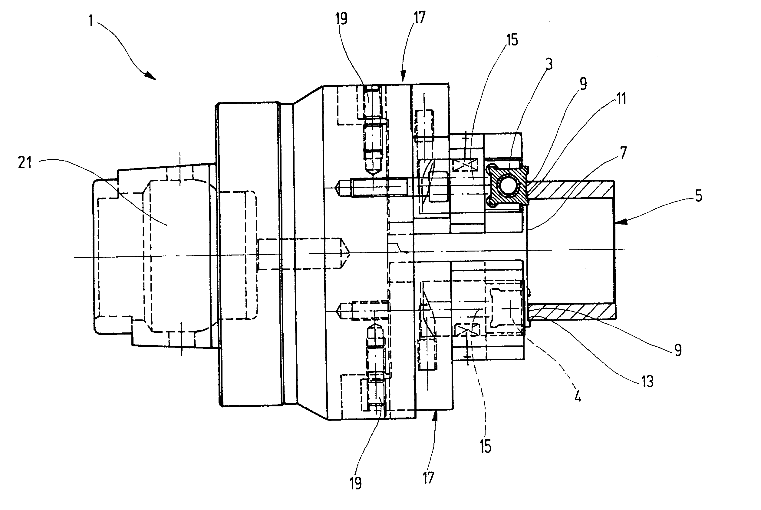
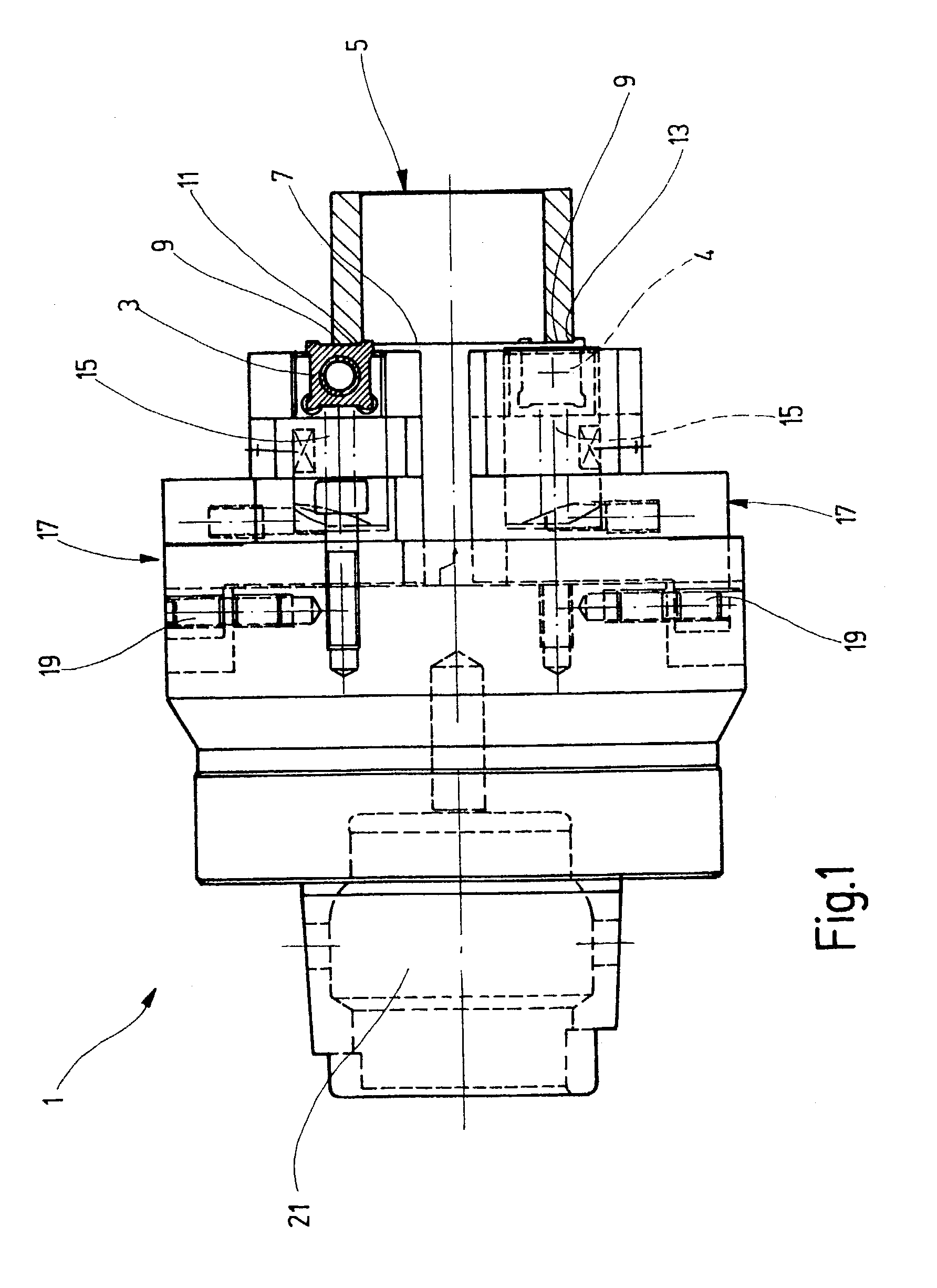
[0017]FIG. 1 shows a tool 1 having a total of two blade plates 3, 4. The plates are identical and can therefore be interchanged. A tubular workpiece 5 having a pipe end 7 is illustrated in section. The blade plates 3, 4 machine and / or produce an end surface 9 of the pipe end 7. Furthermore, in the illustrated position and setting of the tool 1 relative to the workpiece 5, an internal chamfer 11 and an external chamfer 13 are produced and / or machined on the surface 9. The first blade plate 3 is shaped and radially positioned to machine the internal chamfer 11 and the end surface 9 simultaneously. In contrast, the second blade plate 4 is shaped and radially positioned to machine the end surface 9 and the external chamfer 13 simultaneously.

[0018]The length of the tubular workpiece 5 is insignificant for the machining of the end surface 9 and of the chamfers 11, 13. The ends of long pipes can thus be machined just as readily as annular attachments fitted, for example, onto assemblies.

[0...


PUM

PropertyMeasurementUnit
angleaaaaaaaaaa
angleaaaaaaaaaa
diametersaaaaaaaaaa

Abstract

A tool for removing material or machining the end of a pipe. The tool having at least one and preferably two blade plates. Each blade plate includes a first cutter for machining an end surface of the pipe, a second cutter adjacent the first cutter for producing an internal chamfer in the pipe end and a third cutter adjacent the first cutter positioned for producing an external chamfer adjoining the end surface of the pipe end. Devices guide and permit movement of the cutters either radially or axially. The shaping of the cutter is disclosed.

Description

DESCRIPTION[0001]The invention relates to a tool for the material removing machining of pipe ends with cutters for end machining and for forming chamfers.BACKGROUND OF THE INVENTION[0002]Tools of the type disclosed can be used, for example, for providing an end surface having an internal chamfer and an adjoining external chamfer on a pipe end. Three tools of this type can be provided for this purpose, said tools machining and producing the end surface and the chamfers in three working steps. It has been attempted to combine these individual working operations into one working operation using a suitable tool. For this purpose, a tool can be provided with various cutters which machine the pipe end in parallel and thereby machine and / or produce the chamfers and the end surface of the pipe end in one working operation. However, although a tool of this type is suitable for machining the pipe end in one working operation, it has a very complex construction for this purpose and is correspo...

Claims


Application Information

Patent Timeline
Patent Type & Authority Patents(United States)
IPC IPC(8): B23B5/16B23B5/00B23C5/20B23C5/16B23C3/12
CPCB23B5/168B23C3/007B23C5/207B23B2260/004B23C2200/085Y10T408/83B23C2200/201B23C2200/205Y10T408/8713Y10T82/22Y10T408/8598B23C2200/125B23C5/202B23B5/16B23C3/12
Inventor KRESS, DIETER
Owner MAPAL FAB FUR PRAZIONSWERKZEUGE DR KRESS KG
Why Eureka
Try Eureka