Compressible pin assembly

a compression pin and assembly technology, applied in the direction of coupling contact members, coupling device connections, testing/measuring connectors, etc., can solve the problems of reduced conductivity, increased use of expensive gold liquid, and inability to allow all of the gold plating liquid inside the barrel to easily flow out, so as to reduce the amount of gold plating liquid and improve the conductivity through the barrel. , the effect of smooth draining

Active Publication Date: 2005-10-25
MOLEX INC
View PDF13 Cites 32 Cited by
  • Summary
  • Abstract
  • Description
  • Claims
  • Application Information

AI Technical Summary

Benefits of technology

[0005]It is therefore a principal object of the invention to provide a compressible pin assembly that can enable the superfluous gold plating liquid within the barrel to drain out smoothly. This will reduce the amount of gold plati...

Problems solved by technology

Because the barrel is only opened at its front end, the inner portion of the barrel fails to allow all of the gold plating liquid inside the barrel to easily flow out.
Th...

Method used


Image

  • Compressible pin assembly
  • Compressible pin assembly
  • Compressible pin assembly

Examples


Embodiment Construction

[0022]Wherever possible in the following description, like reference numerals will refer to like elements and parts unless otherwise illustrated.

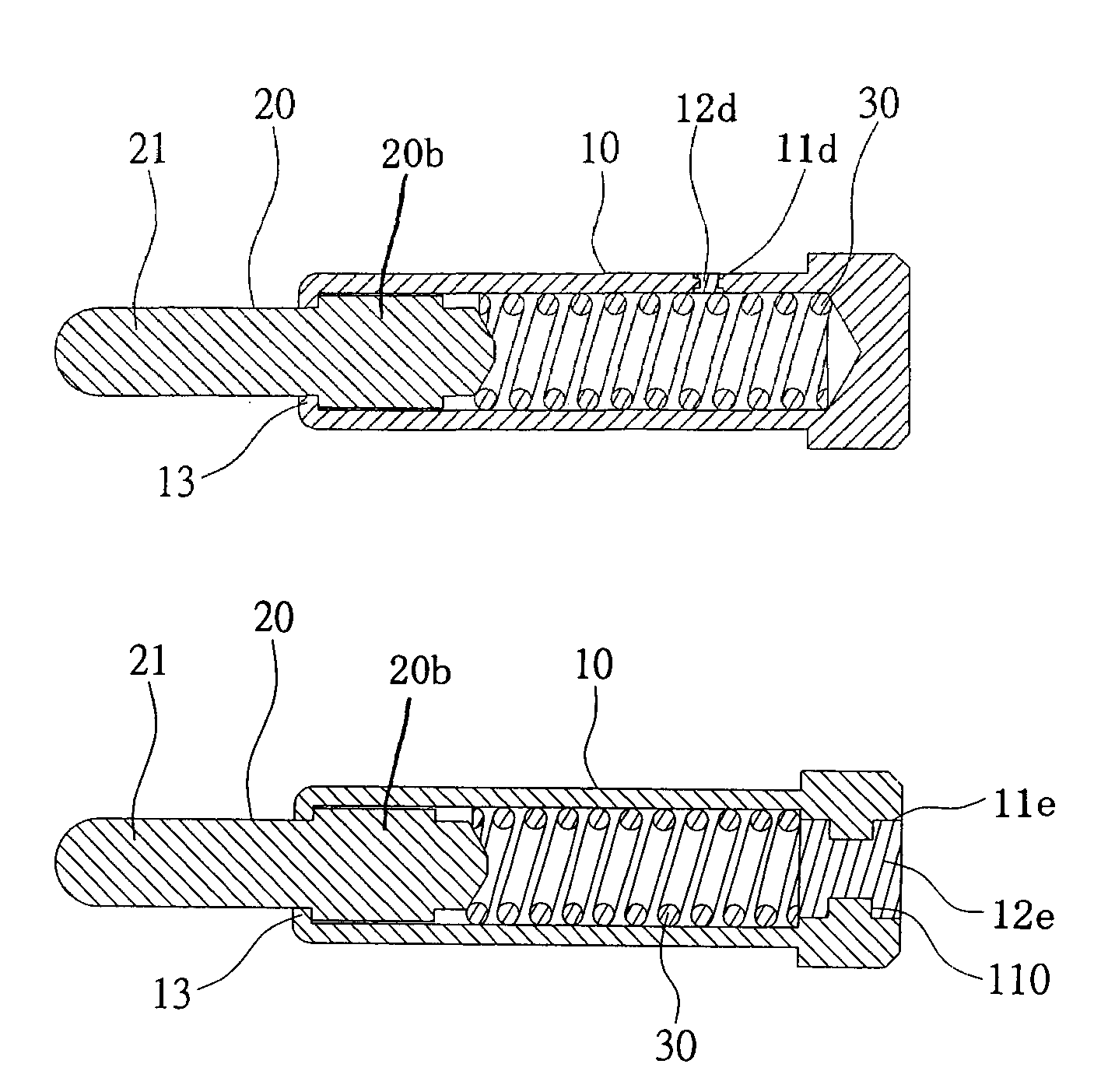
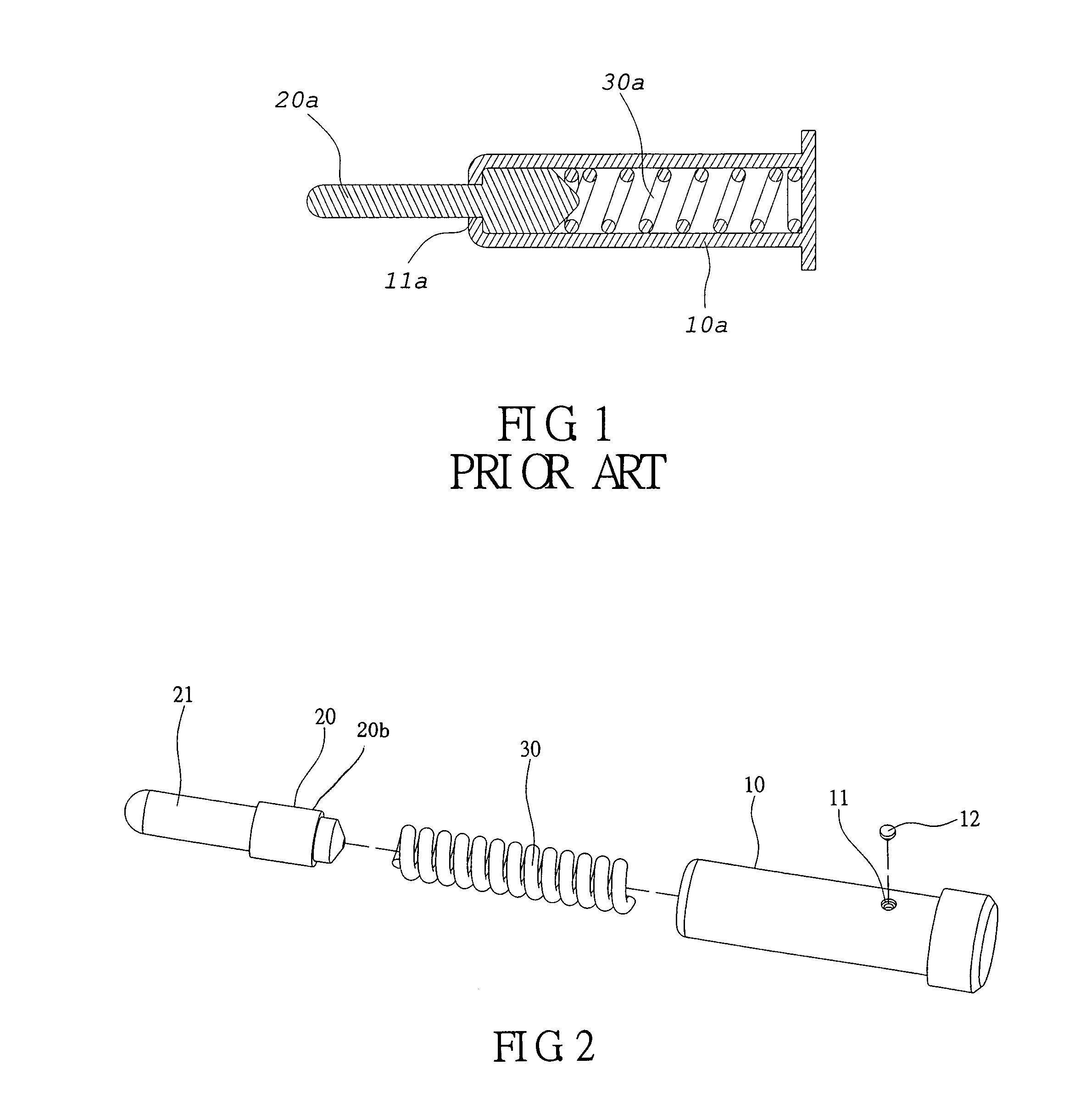
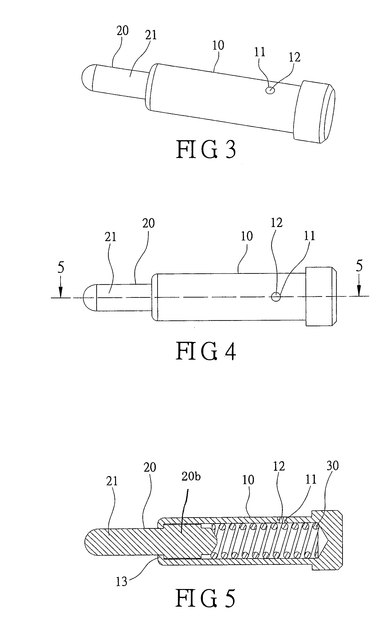
[0023]Referring to FIGS. 2–5, in one embodiment, a compressible pin assembly of the present invention includes a barrel 10, a contact pin 20 and an elastic element 30. The barrel 10 is integrally formed by a metallic material and has a hollow chamber. The barrel 10 has an open front end and a closed rear end. The rear end of the barrel 10 can be fastened into an aperture (not shown) previously formed on a printed circuit board, or can be soldered to a surface of a printed circuit board by means of surface mount technology (SMT) so that the barrel 10 can be electrically connected to the printed circuit board.

[0024]In the preferred embodiment, the barrel 10 has an aperture 11 formed through the circumferential wall of the hollow chamber. The present invention provides a stopper 12 inserted into and sealing the aperture 11 after the barrel is ...


PUM


Abstract

A compressible pin assembly includes a barrel, a contact pin and an elastic element. The contact pin is arranged within the barrel. The contact pin has a contact element. The elastic element is arranged within the barrel to bias the contact pin, so that the contact element is flexibly extended out the front end of the barrel. The barrel has aperture formed therein, which allows superfluous gold plating liquid within the barrel to be eliminated smoothly, after the gold plating process. Thus, the barrel will obtain a more uniform and complete electroplated layer with the use of less gold plating liquid. A stopper will then be inserted into the aperture to prevent impurities from entering the hollow chamber of the barrel. This invention will provide a less expensive compressible pin assembly having greater conductivity.

Description

FIELD OF THE INVENTION[0001]The present invention relates to a compressible pin assembly and, more particularly, to a compressible pin assembly defined as a contact probe for forming an electrical interconnection or providing an electrical contact between two devices.DESCRIPTION OF THE RELATED ART[0002]With reference to FIG. 1, a conventional compressible pin assembly can be defined as a contact probe for forming an electrical interconnection or providing an electrical contact between two devices. The compressible pin assembly generally includes a barrel 10a, a contact element 20a and an elastic element 30a. The barrel 10a is integrally formed by a metallic material and has a hollow chamber. The barrel 10a has an open front end and a closed rear end. The elastic element 30a and the contact element 20a are sequentially placed into the barrel 10a from the front end of the barrel 10a. Then, the front end of the barrel 10a is crimped radially inwardly to form inner dimensions at reduced...

Claims


Application Information

Patent Timeline
IPC IPC(8): H01R13/24H01R13/22
CPCH01R13/2421H01R2201/20H01R12/714
Inventor JING, LU
Owner MOLEX INC
Why Eureka
Try Eureka