Membrane module

a membrane module and membrane technology, applied in the field of membrane modules, can solve the problems of insufficient tightness of the gasket, material dispersion, and inability to predict the final dimensions of the filter elements after the complete termination of the production process, and achieve the effect of saving a large expens

Inactive Publication Date: 2005-10-25
WESTFALIA SEPARATOR AG
View PDF9 Cites 18 Cited by
  • Summary
  • Abstract
  • Description
  • Claims
  • Application Information

AI Technical Summary

Benefits of technology

[0010]The process according to the invention has the very decisive advantage that the dummy can be used again also for the production of replacement seals, which will replace damaged seals, which spares a large expense.

Problems solved by technology

This can lead to a distortion of the material, so that the filter elements are no longer linear in shape, but—to exaggerate somewhat—assume a banana shape.
Also, the final dimensions of the filter elements after the complete termination of the production process are not predictable.
If a prefabricated gasket is attached onto the terminal region of a filter element, an excessive extension of the gasket, may occur, each time depending on the outer dimension of the filter element, in some cases, while in other cases, such attachment can lead to the circumstance that the gasket is no longer sufficiently tightly seated, or is seated with play in the terminal region.
In the case of excessive elongation, this will lead sooner or later to a premature failure of the gasket, and in the case of an under-dimension, leakage can occur.
After a longer operation, this leads to the fatigue of the seal material.
The seals are then no longer capable of function and break down.
This involves a considerable expense.

Method used


Image

  • Membrane module
  • Membrane module
  • Membrane module

Examples


Embodiment Construction

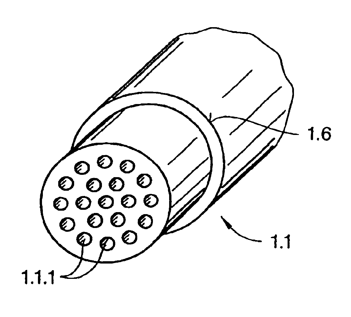
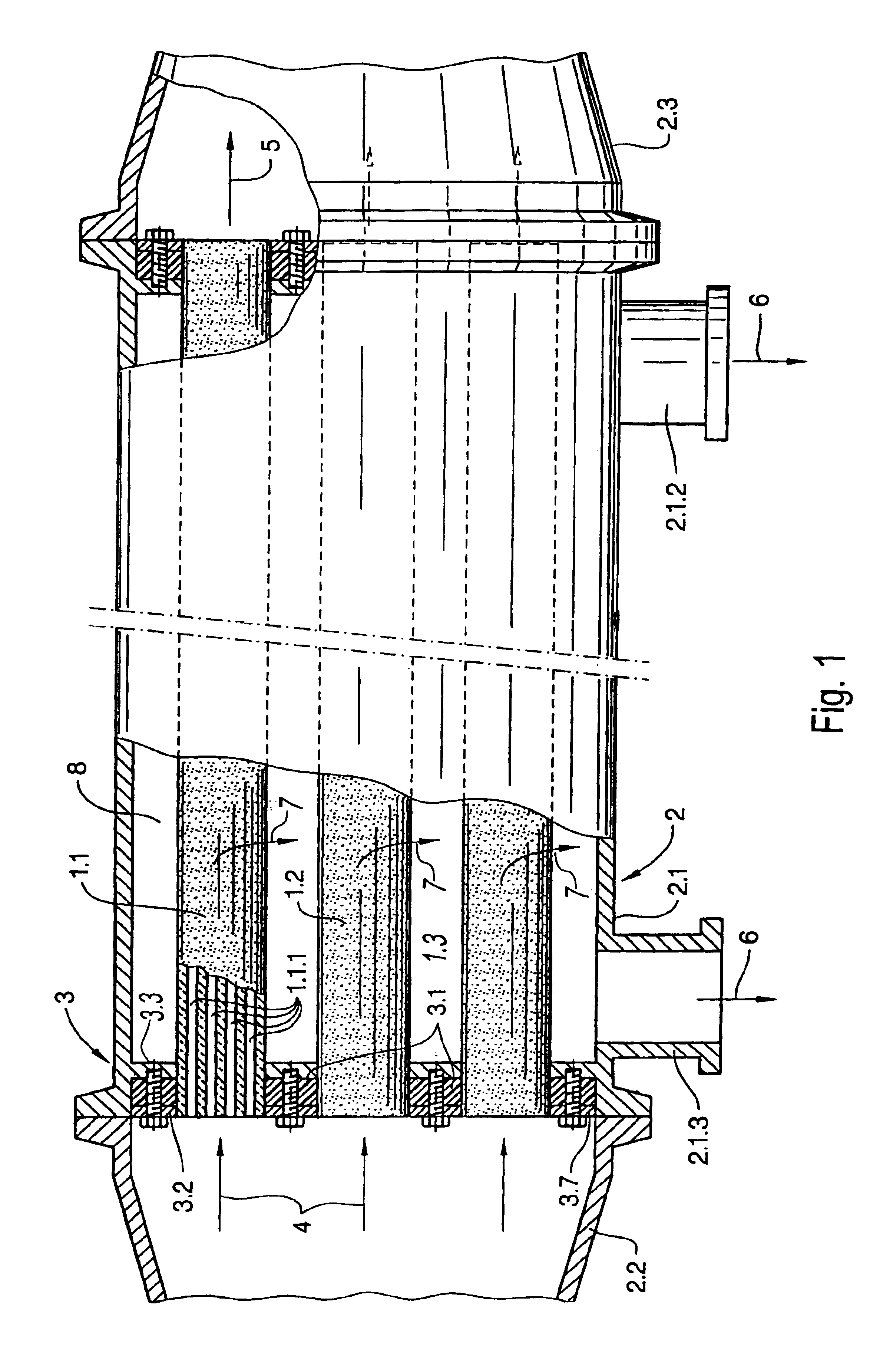
[0020]The membrane module shown in FIG. 1 comprises a number of filter elements 1.1, 1.2, 1.3. The filter elements are rod-shaped. They have a cylindrical configuration and a circular cross-section. A multiple number of channels 1.1.1 pass through each filter element.

[0021]The membrane module also comprises a housing 2, which encloses filter elements 1.1, 1.2, 1.3. Housing 2 is also circular-shaped. It has a main part 2.1 as well as conical connecting parts 2.2 and 2.3. Main part 2.1 has two discharge connections 2.1.2 and 2.1.3.

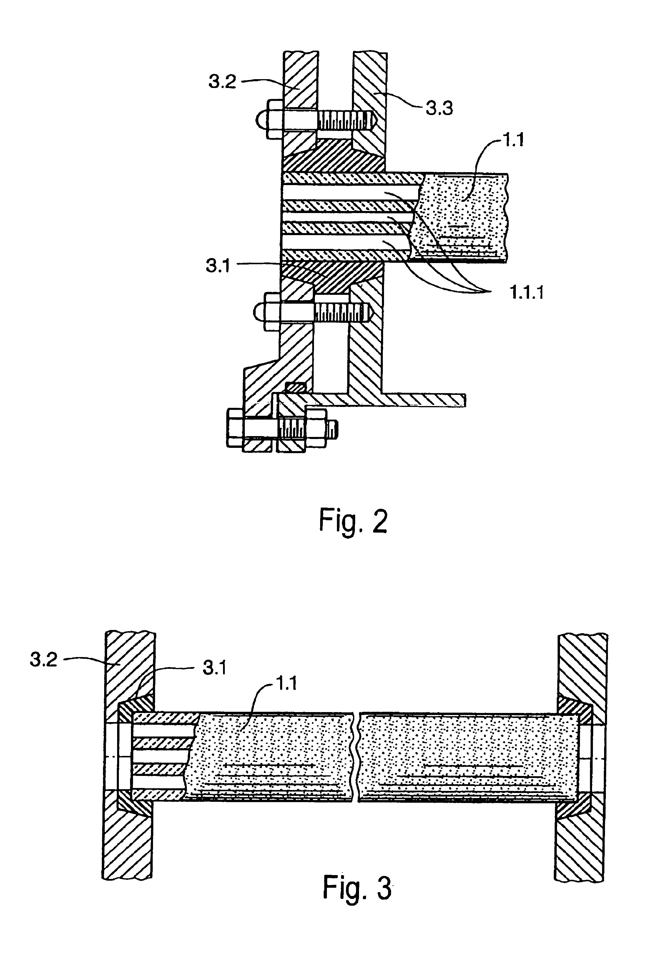
[0022]A cover unit 3, which is found each time at the ends of filter elements 1.1, 1.2 and 1.3, can also be discerned. Each cover unit 3 comprises a seal 3.1, an outer plate 3.2 and an inner plate 3.3. The inner plate 3.3 is made up in one part with main part 2.1 of housing 2 in this case. Components 3.1, 3.2 and 3.3 are joined together like a sandwich and are held together by screws.

[0023]Channels 1.1.1 of filter elements 1.1, 1.2, and 1.3 are loaded with t...


PUM

PropertyMeasurementUnit
diameteraaaaaaaaaa
shapeaaaaaaaaaa
axial thrust forceaaaaaaaaaa

Abstract

The invention relates to a method for producing a membrane module, comprising a plurality of bar-shaped ceramic filter elements disposed parallel to each other and stretched on the ends of the bay by covers, which extend perpendicular to said bars. Said modules also comprise sealing elements provided in-between the ends of the bars in addition to holes in the covers. The invention is characterized by the following features: initially, the individual sealing element is partially produced by finishing the inner hole thereof intended for surrounding the end of the bar to its final size while the outer surface of the sealing element remains unprocessed so that a sealing blank is formed; the sealing blank is then inserted into a support having outer dimensions in the insertion area corresponding to the mean outer dimensions of all filter elements or a plurality of filter elements. The outer surface of the sealing blank inserted into the support is processed to its set size thereby forming the finished sealing element. The finished sealing element is inserted into the end area of a filter element and assembled along with the other usual elements to form a finished membrane module.

Description

FIELD OF THE INVENTION[0001]The invention concerns a membrane module. Such modules are known. They serve for the process of separating a component from a liquid or a gas. They comprise a number of rod-shaped ceramic filter elements, which are arranged parallel to one another. Groups of such filter elements are assembled for the most part and are clamped at each end by means of covers. The covers thus run perpendicularly to the rods. The covers have a number of openings corresponding to the number of filter elements. The inside diameter of each opening is thus generally somewhat larger than the outer dimension of the terminal region of the individual rod. The intermediate space is filled by a sealing ring.BACKGROUND OF THE INVENTION[0002]Such a membrane module has become known, for example, from EP 0 270, 051.[0003]The production of the individual filter element is associated, among other things, with an annealing process, which requires maximal temperatures. This can lead to a disto...

Claims


Application Information

Patent Timeline
Patent Type & Authority Patents(United States)
IPC IPC(8): B01D63/06B23P11/00
CPCB01D63/061B01D63/066B01D71/024B01D2313/21B01D2319/04B01D65/003
Inventor BLASE, DIETERFEUERPEIL, HANS-PETER
Owner WESTFALIA SEPARATOR AG
Why Eureka
Try Eureka