Key switch device having high drawability

Inactive Publication Date: 2005-10-25
TSAI HUO LU
View PDF4 Cites 20 Cited by
  • Summary
  • Abstract
  • Description
  • Claims
  • Application Information

AI Technical Summary

Benefits of technology

[0007]An object of the present invention is to provide a key switch device with a strong structure for a cap support so that t

Problems solved by technology

The aforesaid prior art suffers from a problem in that, when the key switch device is subjected to a drawability test, the first frame 6 is prone to stretch outward and deform, thus lowering the drawability of the key switch device.
In addition, due to the increasing demand for the miniaturization of key switch devices, the

Method used


Image

  • Key switch device having high drawability
  • Key switch device having high drawability
  • Key switch device having high drawability

Examples


Example

[0022]Before the present invention is described in greater detail, it should be noted that same reference numerals have been used to denote like elements throughout the specification.

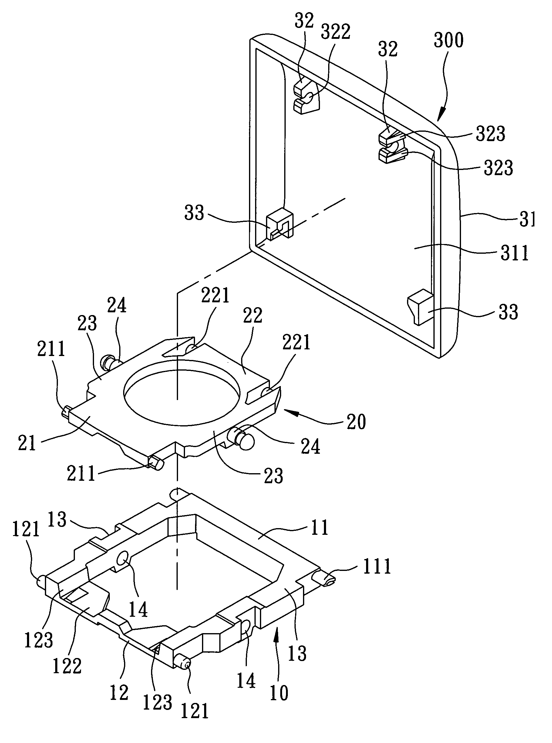
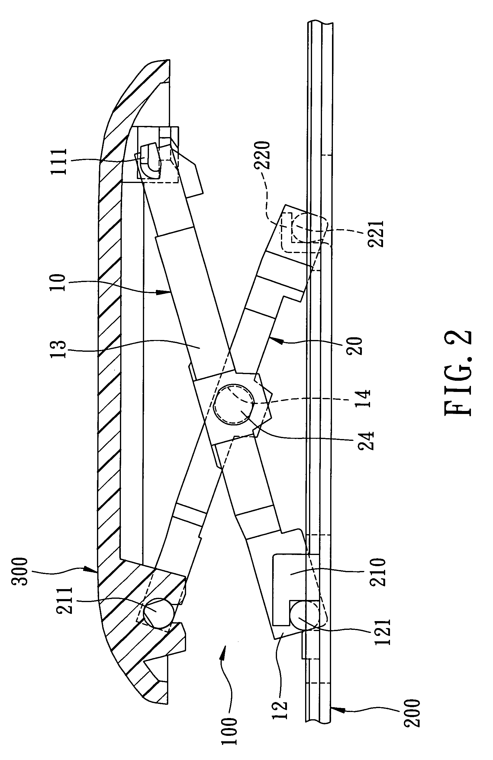
[0023]Referring to FIG. 2, the first preferred embodiment of the key switch device according to the present invention includes a cap support 100 mounted on a base 200 and a key cap 300 supported by the cap support 100. The base 200 has first retention members 210 and second retention members 220 which project upward from the base 200. The cap support 100 includes two intersecting first and second frames 10 and 20 which are connected pivotally to each other and which are made of plastic by injection molding.

[0024]Referring to FIGS. 3 and 4, the first frame 10 is configured as a four-sided closed frame and includes a first top member 11, a first bottom member 12 and two spaced apart first lateral members 13 interconnecting the first top and bottom members 11 and 12. Latch pins 111 project outwardly and re...


PUM


Abstract

A key switch device has a cap support that supports a key cap on a base. The cap support includes intersecting first and second frames which are connected pivotally to each other. The first frame has a pair of through holes, whereas the second frame has a pair of retaining pins for connection with the through holes. Each retaining pin has an outermost head, an inner neck part and a shoulder formed between the outermost head and the inner neck part. The first and second frames are connected to each other by inserting each retaining pin into the corresponding through hole until the outermost head projects outwardly of the through hole and the shoulder engages an outer side of the first frame.

Description

BACKGROUND OF THE INVENTION[0001]1. Field of the Invention[0002]This invention relates to a key switch device, more particularly to a key switch device for computers and other data processing devices.[0003]2. Description of the Related Art[0004]As shown in FIG. 1, a typical key switch device includes a base support composed of a substrate 1, a membrane circuit member 2 mounted on the substrate 1, a resilient layer 3 superimposed upon the membrane circuit member 2, and a plurality of key caps 5 (only one is shown for simplicity) each of which is mounted on the substrate 1 through a cap support 4.[0005]Each cap support 4 includes two intersecting first and second frames 6 and 7 which are interconnected pivotally to each other. The first frame 6 has a substantially U-shape and includes two lateral rods 601 and an intermediate member 602 connected to the lateral rods 601. Each lateral rod 601 is provided with a retaining hole 603 at the middle thereof. The second frame 7 is a four-sided...

Claims


Application Information

Patent Timeline
IPC IPC(8): H01H13/70H01H13/705H01H3/12
CPCH01H3/125
Inventor TSAI, HUO-LU
Owner TSAI HUO LU
Why Eureka
Try Eureka