Method and apparatus for positioning pulses in time

a technology of positioning pulses and time, applied in the field of impulse transmission systems, can solve the problems of limiting the performance of systems that use continuous sinusoidal waveforms, hardware limitation on the minimum pulse-to-pulse time, and the use of very little power of impulse radio transmitters to generate noise-like communication signals

Inactive Publication Date: 2005-10-25
HUMATICS CORP
View PDF17 Cites 118 Cited by
  • Summary
  • Abstract
  • Description
  • Claims
  • Application Information

AI Technical Summary

Problems solved by technology

As a result, the impulse radio transmitter uses very little power to generate noise-like communication signals for use in multiple-access communications, radar and positioning applications, among other things.
Because of the extremely high achievable processing gains, the impulse radio systems are relatively immune to unwanted signals and interference, which limit the performance of systems that use continuous sinusoidal waveforms.
Because of practical limitations associated with arbitrarily positioning of pulses in adjacent frames, each frame may have to be divided into allowable and non-allowable time regions for positioning a pulse.
One such limitation is associated with hardware limitation on minimum pulse-to-pulse time for respective positioning of two pulses on adjacent frames arbitrarily.

Method used


Image

  • Method and apparatus for positioning pulses in time
  • Method and apparatus for positioning pulses in time
  • Method and apparatus for positioning pulses in time

Examples


Embodiment Construction

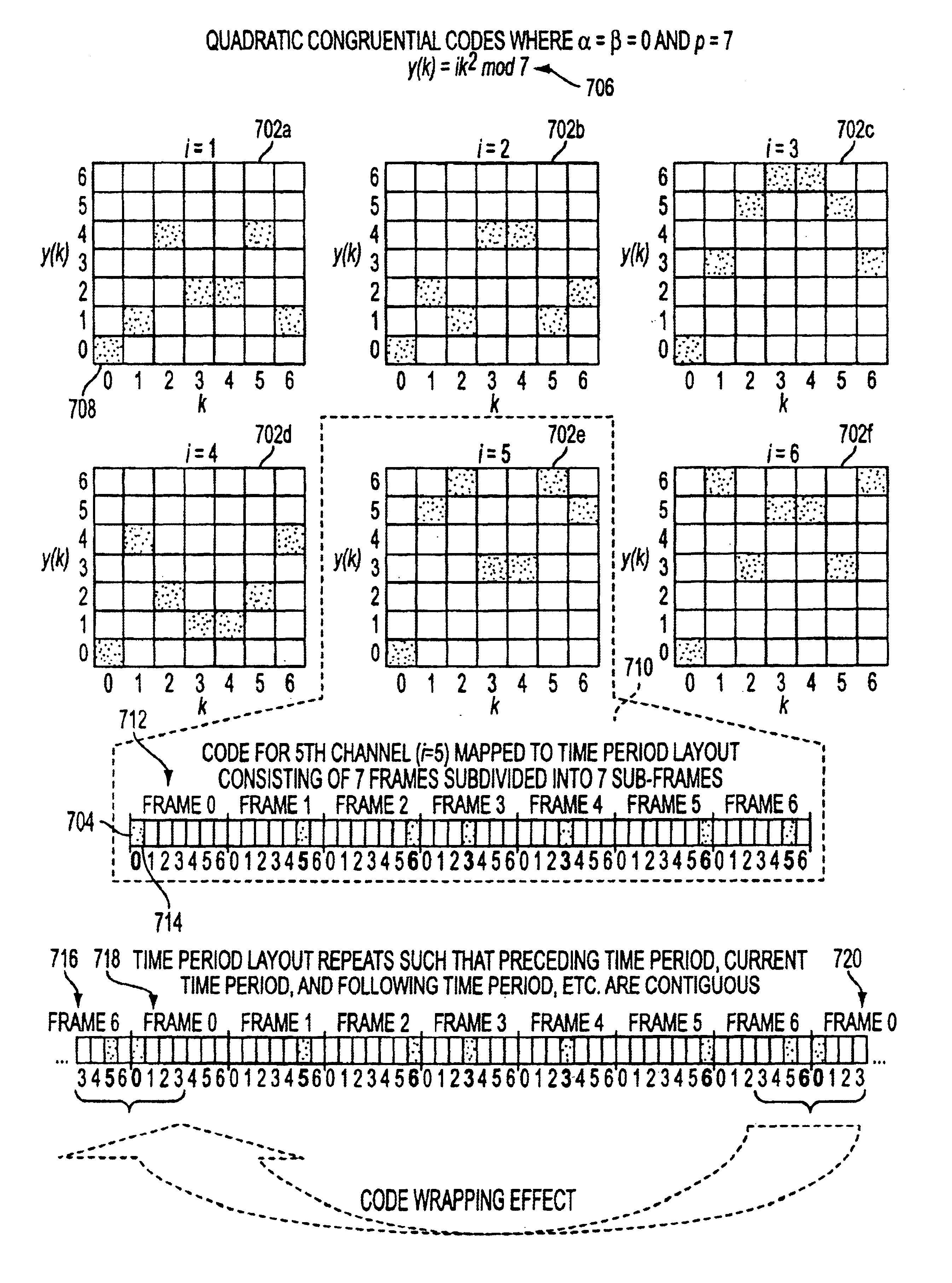
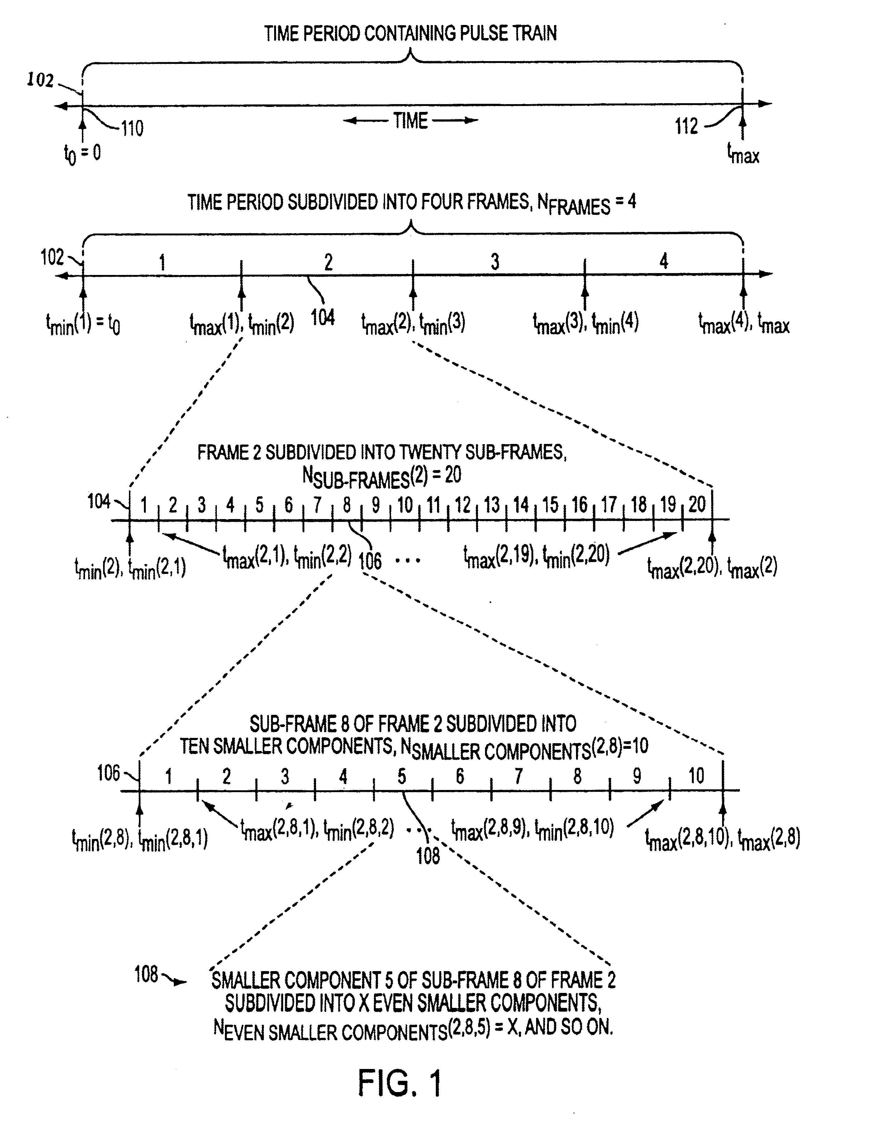
[0057]The present invention provides a method of using a generated code to specify positions and other characteristics of pulses within a pulse train. Usually, each generated code consists of a set or a number of code element values. The method of the invention involves defining a layout of the time period over which the pulses arc overlaid. A mapping approach maps the code element values to pulse positions over the layout based on the generated code. In an exemplary embodiment, the code is generated using a numerical code generation technique, and code element values are mapped to pulse positions in accordance with the defined time period layout and code mapping approach.
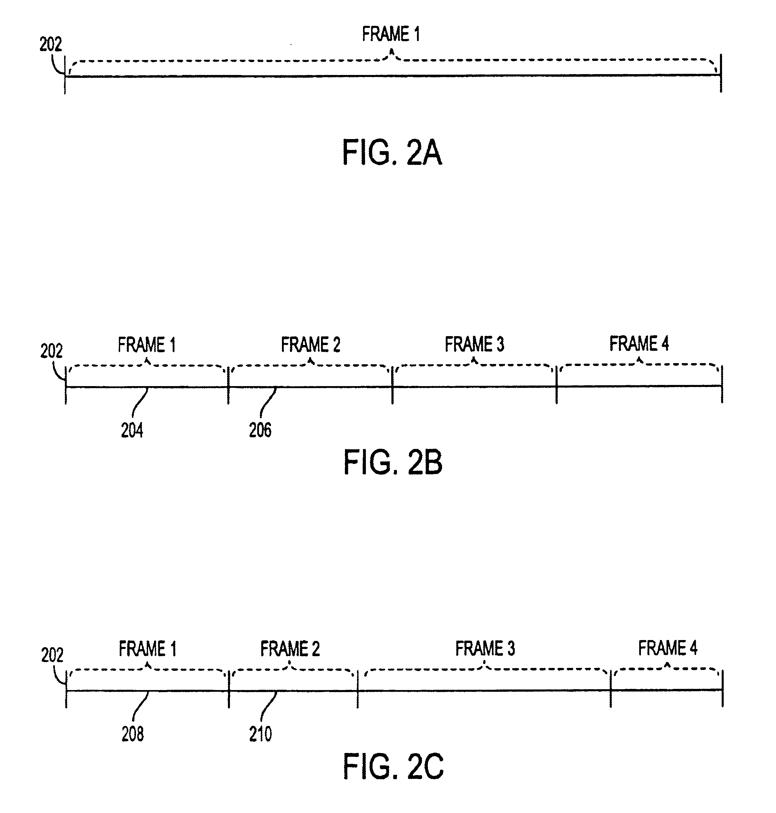
Time Period Layouts

[0058]In a pulse transmission system, a sequence of pulses known as a pulse train is transmitted and received over a period of time such that the relative positioning of the pulses in time defines a channel used by the system to transmit information. These pulse trains or some combination of diff...


PUM


Abstract

A coding method specifies pulse positioning over time according to a time layout about a time reference where a pulse can be placed at any location within the time layout. The method generates time-hopping codes having predefined properties, and a coded pulse train based on the time-hopping codes and the time layout. The time reference may be fixed or non-fixed and can be a time position of a preceding or a succeeding pulse. In addition, the predefined properties can be autocorrelation, cross-correlation, or spectral properties.

Description

CROSS-REFERENCE TO OTHER APPLICATIONS[0001]This is a Continuation-in-Part of application Ser. No. 09 / 592,248 filed Jun. 12, 2000.[0002]U.S. patent application No. 09 / 638,192 entitled “A METHOD FOR SPECIFYING NON-TEMPORAL PULSE CHARACTERISTICS”, filed concurrently herewith.[0003]U.S. patent application No. 09 / 638,046 entitled “A METHOD AND APPARATUS FOR APPLYING CODES HAVING PRE-DEFINED PROPERTIES”, filed concurrently herewith, now U.S. Pat. No. 6,671,310.[0004]U.S. patent application No. 09 / 637,878 entitled “A METHOD AND APPARATUS FOR POSITIONING PULSES USING A LAYOUT HAVING NON-ALLOWABLE REGIONS”, filed concurrently herewith.[0005]U.S. patent application No. 09 / 638,151 entitled “A METHOD AND APPARATUS FOR MAPPING PULSES TO A NON-FIXED LAYOUT”, filed concurrently herewith.[0006]U.S. patent application No. 09 / 638,152 entitled “A METHOD AND APPARATUS FOR SPECIFYING PULSE CHARACTERISTICS USING A CODE THAT SATISFIES PREDEFINED CRITERIA”, filed concurrently herewith, now abandoned.[0007]...

Claims


Application Information

Patent Timeline
Patent Type & Authority Patents(United States)
IPC IPC(8): H03K7/04H03K7/00H03K9/00H03K9/04H04B1/69
CPCH03K7/04H04B1/7176H04B2001/6908
Inventor RICHARDS, JAMES L.ROBERTS, MARK D.PENDERGRASS, MARCUS H.
Owner HUMATICS CORP
Why Eureka
Try Eureka