Power management system for street sweeper

a power management system and street sweeper technology, applied in the direction of cleaning filter means, suction cleaners, construction, etc., can solve the problems of insufficient horsepower to operate the brushes, insufficient power to operate at a reduced performance level, etc., to achieve a cleaner sweeping operation, reduce the performance level, and the effect of reducing the speed

Inactive Publication Date: 2005-11-01
WAYNE SWEEPERS LLC
View PDF17 Cites 29 Cited by
  • Summary
  • Abstract
  • Description
  • Claims
  • Application Information

AI Technical Summary

Benefits of technology

[0014]One advantage of this system is that one or more pumps may be utilized to operate the vacuum fan and sweeping mechanism as the engine speed (and pump speed) varies. As a result of providing the sweeper with the aforesaid feature, a cleaner sweeping operation can now be attained since the optimum vacuum fan speed and broom speed can be maintained at as low engine speeds as 800 RPM. This allows the operator to move the sweeping vehicle slowly through a conventional drive train system while maintaining the vacuum fan, brooms and conveyor at preferred ...

Problems solved by technology

At lower engine speeds, such as below 1000 RPM, there may not be adequate horsepower to operate the brushes, conveying system, and dry dust control vacuum fan at the required ...

Method used


Image

  • Power management system for street sweeper
  • Power management system for street sweeper
  • Power management system for street sweeper

Examples


Embodiment Construction

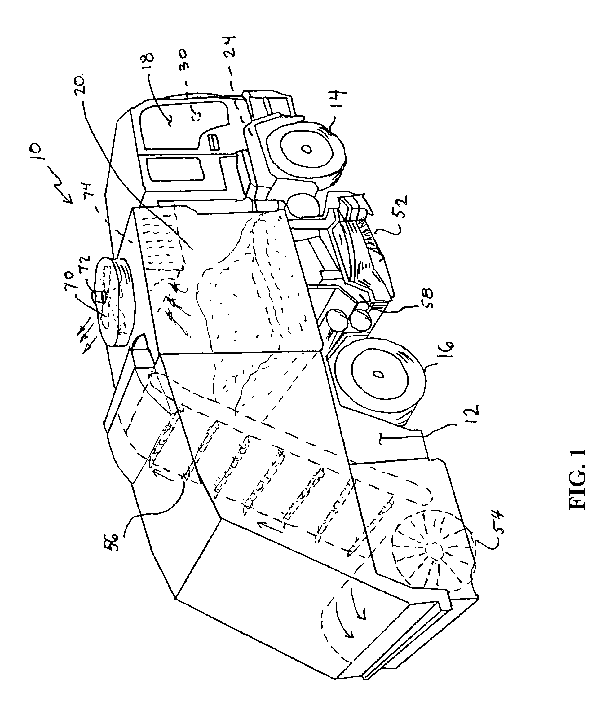
[0019]In FIG. 1 a self-propelled, four-wheeled street sweeper 10 is shown of the type that is particularly adapted to travel at relatively high speeds on open highways when traveling to and from areas to be swept and which is also capable of efficiently operating at slower speeds when sweeping streets.

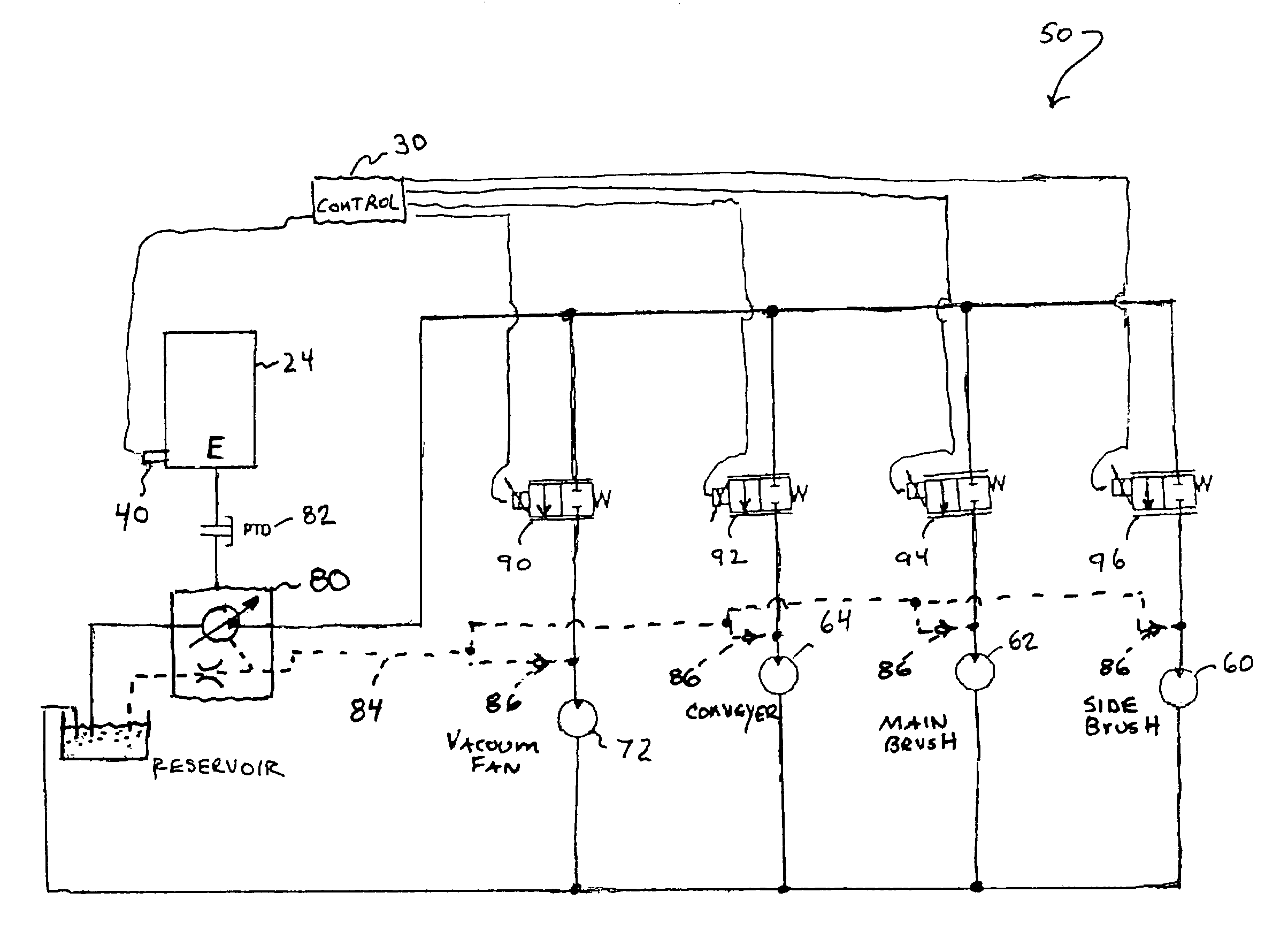
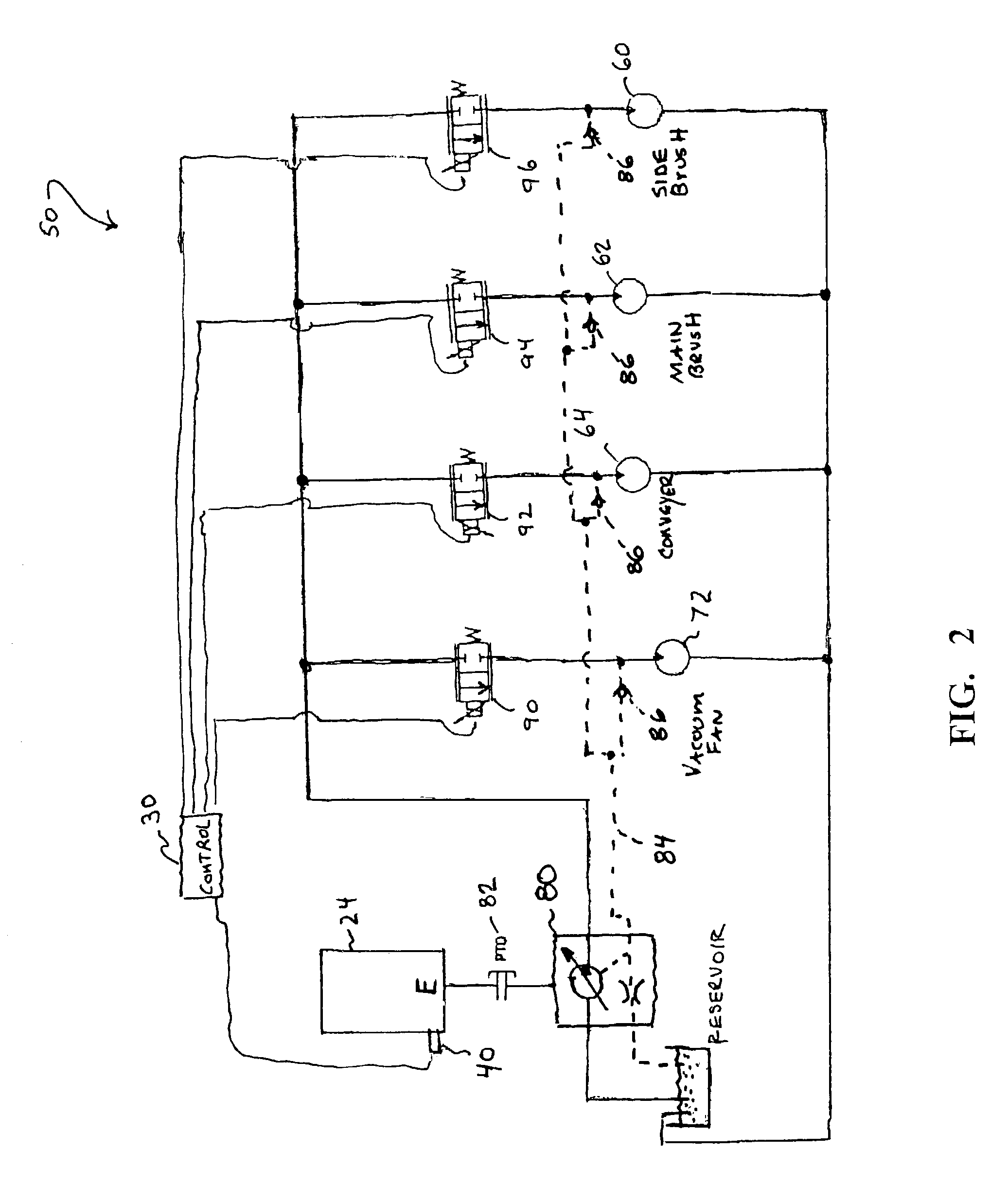
[0020]The street sweeper 10 includes a main frame 12 that is supported by a front axle mounted on a pair of front wheels 14 and a rear axle mounted on a pair of rear wheels 16. An operator's cab 18 is disposed at the front end of sweeper 10 with a refuse collecting hopper 20 supported on the main frame 12 immediately behind cab 18. An engine 24 provides the drive to power wheels 16 for travel along a street surface at suitable speeds in accordance with traffic conditions. As described herein, engine 24 also provides power during the sweepers' mode of operation. As further described herein, a power management device including a control unit 30 and an engine speed sensor 40 are utilized ...


PUM


Abstract

A power management system for a surface maintenance machine, such as a street sweeper is disclosed. The system includes a variable speed engine for transporting the surface maintenance machine, a hydraulic pump powered by the engine, a vacuum fan motor powered by the hydraulic pump, an engine speed sensor coupled to the engine, an electric proportional valve coupled between the hydraulic pump and the vacuum fan motor, said valve for selectively restricting a flow rate to the vacuum fan motor, and a control unit operatively coupled to the engine speed sensor and the proportional valve, said control unit receiving engine speed information from the engine speed sensor and communicating a predetermined signal to the proportional valve to control the flow rate to the vacuum fan motor as a function of engine speed. A method of managing engine power from a single-engine street sweeper is also disclosed.

Description

BACKGROUND OF THE INVENTION[0001]1. Field of the Invention[0002]This invention relates to a new and improved street sweeper and more particularly to a new and improved power management system for operating the various components of a street sweeper including such components as the vacuum fan, side brooms, the conveyor, and the like.[0003]2. Description of the Prior Art[0004]Single-engine street sweepers, such as disclosed in U.S. Pat. Nos. 4,343,060, and 4,328,603, each incorporated by reference herein, use the vehicle chassis engine to power the vehicle as well as the sweeping apparatus. Known sweepers typically use one or more hydraulic pumps driven by one or more power transmissions, such as a power-take-off (PTO) attached to the vehicle transmission.[0005]Street sweepers operate at a variety of sweeping speeds, often up to 15 mph or more, and are required to negotiate slowly around obstacles, such as parked cars, while sweeping. Engine speed varies substantially as the travel sp...

Claims


Application Information

Patent Timeline
IPC IPC(8): E01H1/04E01H1/08E01H1/00
CPCE01H1/042E01H1/0854
Inventor ALOWONLE, MUSIBAU O.BLOCK, CRAIG D.ERKO, ROBERT J.MILUN, RICHARD F.
Owner WAYNE SWEEPERS LLC
Why Eureka
Try Eureka