
Hydraulic control system based on single-engine road sweeper

A hydraulic control system and single-engine technology, applied in road cleaning, mechanical equipment, cleaning methods, etc., can solve the problems of high noise, increased manufacturing cost of sweeping vehicles, increased fuel consumption, etc., to reduce exhaust emissions and noise, and save fuel Consumption and reduction of sub-engine effects

Inactive Publication Date: 2014-09-10
CHANGAN UNIV
View PDF4 Cites 13 Cited by
  • Summary
  • Abstract
  • Description
  • Claims
  • Application Information

AI Technical Summary

Problems solved by technology

When the vehicle is cleaning, the running power provided by the chassis engine only accounts for 20% to 30% of the total engine power, and the engine does not work in the best economic zone, which will inevitably lead to increased fuel consumption, increased noise, and reduced exhaust gas volume. Then it increases; while the auxiliary engine only works during the cleaning operation, its power utilization rate is also very low, and the noise of the two engines is louder at the same time, and the main engine of the cleaning vehicle runs at a low speed when it is working, and the phenomenon of "big horse and small car" appears ; At the same time, the relevant accessories and control devices required by the auxiliary engine must be configured, thereby increasing the manufacturing cost of the sweeper

Method used


Image

  • Hydraulic control system based on single-engine road sweeper
  • Hydraulic control system based on single-engine road sweeper
  • Hydraulic control system based on single-engine road sweeper

Examples


Embodiment Construction

[0017] The present invention will be described in further detail below in conjunction with the accompanying drawings.

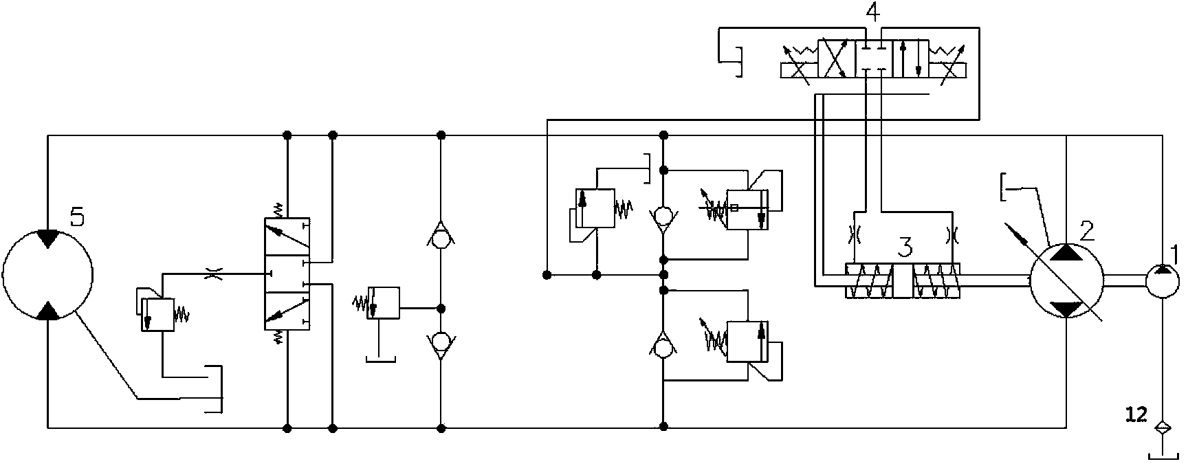
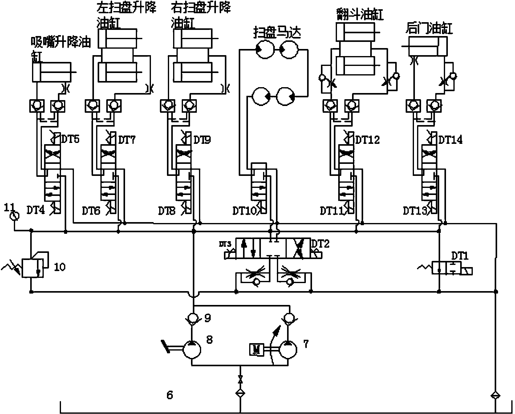
[0018] see figure 1 , 2. The present invention includes a walking hydraulic control system and a cleaning hydraulic control system; the walking hydraulic control system includes a three-position four-way valve 4 whose control end is connected to the accelerator pedal, and the output end of the three-position four-way valve 4 is connected through an electromagnetic floating valve 3 Bidirectional variable variable pump 2, the oil outlet of bidirectional variable variable pump 2 is connected to the oil inlet of bidirectional quantitative motor 5, and the oil inlet of bidirectional variable variable pump 2 is connected to the oil outlet of bidirectional quantitative motor 5 to form a circulation loop; A charge pump 1 for auxiliary work is connected, and a filter 12 is arranged on the inlet pipeline of the charge pump 1; the cleaning hydraulic control system inclu...


PUM


Abstract

A hydraulic control system based on a single-engine road sweeper comprises a walking hydraulic control system and a sweeping hydraulic control system. The walking hydraulic control system comprises a three-position four-way valve with the control end connected with an accelerator pedal, the output end of the three-position four-way valve is connected with a bidirectional variable pump through an electromagnetic floating valve, and the bidirectional variable pump is respectively connected with an oil inlet and an oil outlet of a bidirectional constant displacement motor to form a circulating loop. The sweeping hydraulic control system comprises an oil tank and transfer cases arranged in parallel, the transfer cases are controlled by two electromagnetic reversing valves with the opposite control actions, the oil tank is connected with the transfer cases through pipelines, and hydraulic pumps are arranged on the connecting pipelines. A disc sweeping motor is controlled by an independent motor electromagnetic reversing valve, and two electromagnetic reversing valves used for flow division are arranged between the electromagnetic reversing valve and the oil tank in parallel. An overflow valve and an unloading electromagnetic reversing valve are respectively connected between the oil tank and the transfer cases. An auxiliary engine is eliminated, the habit of a drive for driving a vehicle is not changed, and a large amount of fuel is saved.

Description

technical field [0001] The invention relates to a vehicle automatic control system, in particular to a hydraulic control system for a road sweeper based on a single engine. Background technique [0002] As my country's urbanization process is getting faster and faster, cities are getting bigger, roads, squares, and parks are increasing, and urban cleaning and cleaning work has become more and more important and arduous. Therefore, the number of sweeping vehicles continues to increase, but the development of sweeping vehicles So far, there is no single-engine sweeper on the market, all are dual-engine models, that is, the chassis engine only provides the power of the driving system, and the auxiliary engine is responsible for providing power for the cleaning work device. When the vehicle is cleaning, the running power provided by the chassis engine only accounts for 20% to 30% of the total engine power, and the engine does not work in the best economic zone, which will inevita...

Claims


Application Information

Patent Timeline
IPC IPC(8): F15B11/00F15B11/04E01H1/05
Inventor 屈孝和李强范帅朱杰尧刘飞霞
Owner CHANGAN UNIV
Learn More