
Method and apparatus for energy generation utilizing temperature fluctuation-induced fluid pressure differentials

a technology of fluid pressure differential and temperature fluctuation, applied in the direction of mechanical equipment, mechanical power devices, machines/engines, etc., can solve the problems of limited benefits, no prior art device can generate motive power on a continuing renewable basis, and limited benefits derived

Inactive Publication Date: 2005-11-01
CORCORAN CRAIG C
View PDF61 Cites 66 Cited by
  • Summary
  • Abstract
  • Description
  • Claims
  • Application Information

AI Technical Summary

Benefits of technology

[0016]It is therefore a primary object of the present invention to provide an apparatus and method for generating energy that relies primarily upon natural renewable energy sources to create differing percentage temperature fluctuations between captive compressed fluid in at least two containers relative to each other and use the resulting pressure differential between the two containers to urge a flow of a compressed fluid that will drive a motive power source as it flows between the two containers.
[0021]Still another object of the invention is to utilize a closed system so that the compressed medium remains captive within the system, thus avoiding the need to continually repressurize or replenish the working medium.

Problems solved by technology

The benefits derived are limited, however, since percent increases in pressure are applied to an ambient pressure base.
The benefits derived are a direct result of and are limited by the continuous energy usage requirements of the air compressor.
None of the prior art devices generate motive power on a continuing renewable basis utilizing temperature fluctuations to cycle captive compressed fluid.

Method used


Image

  • Method and apparatus for energy generation utilizing temperature fluctuation-induced fluid pressure differentials
  • Method and apparatus for energy generation utilizing temperature fluctuation-induced fluid pressure differentials
  • Method and apparatus for energy generation utilizing temperature fluctuation-induced fluid pressure differentials

Examples


Embodiment Construction

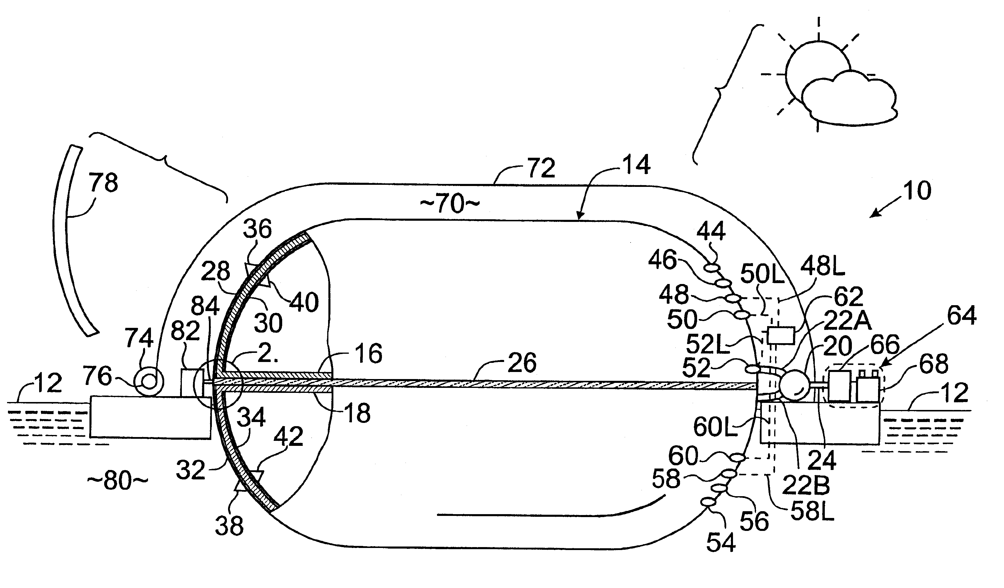
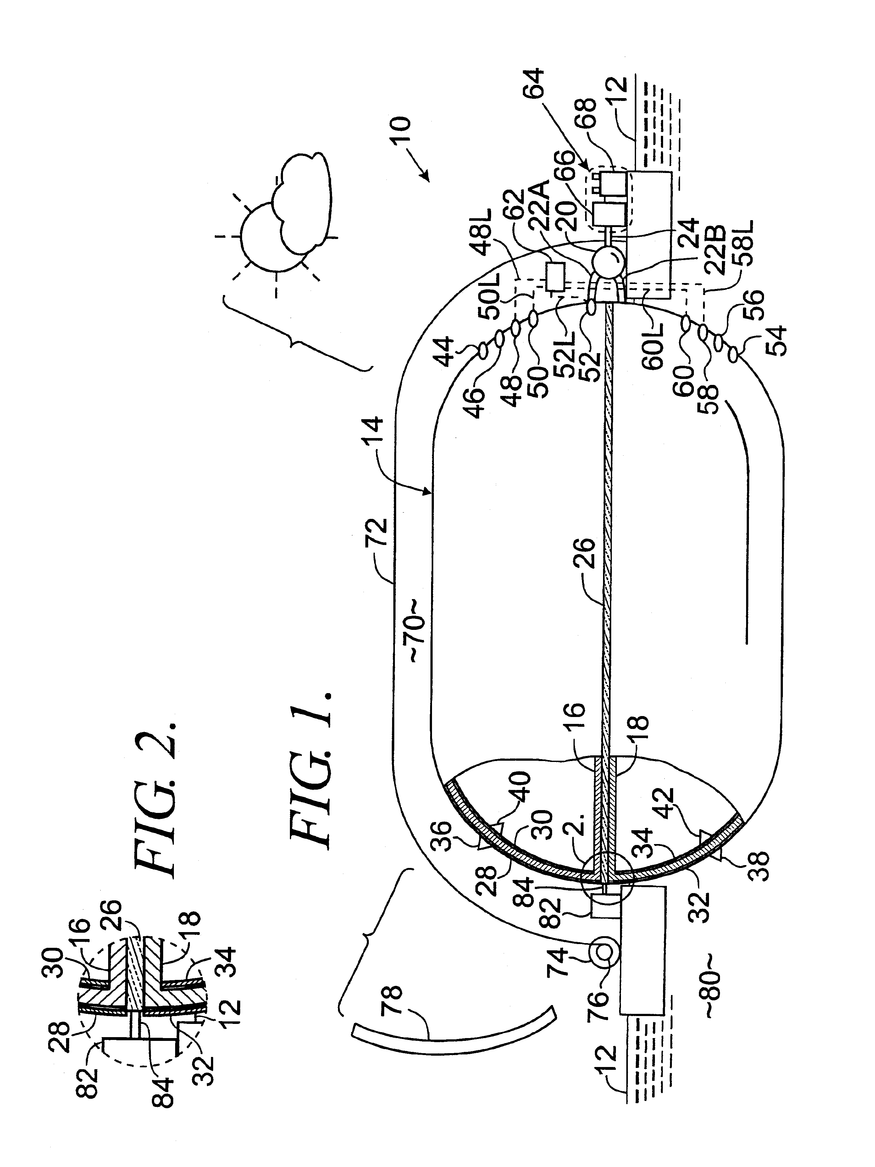
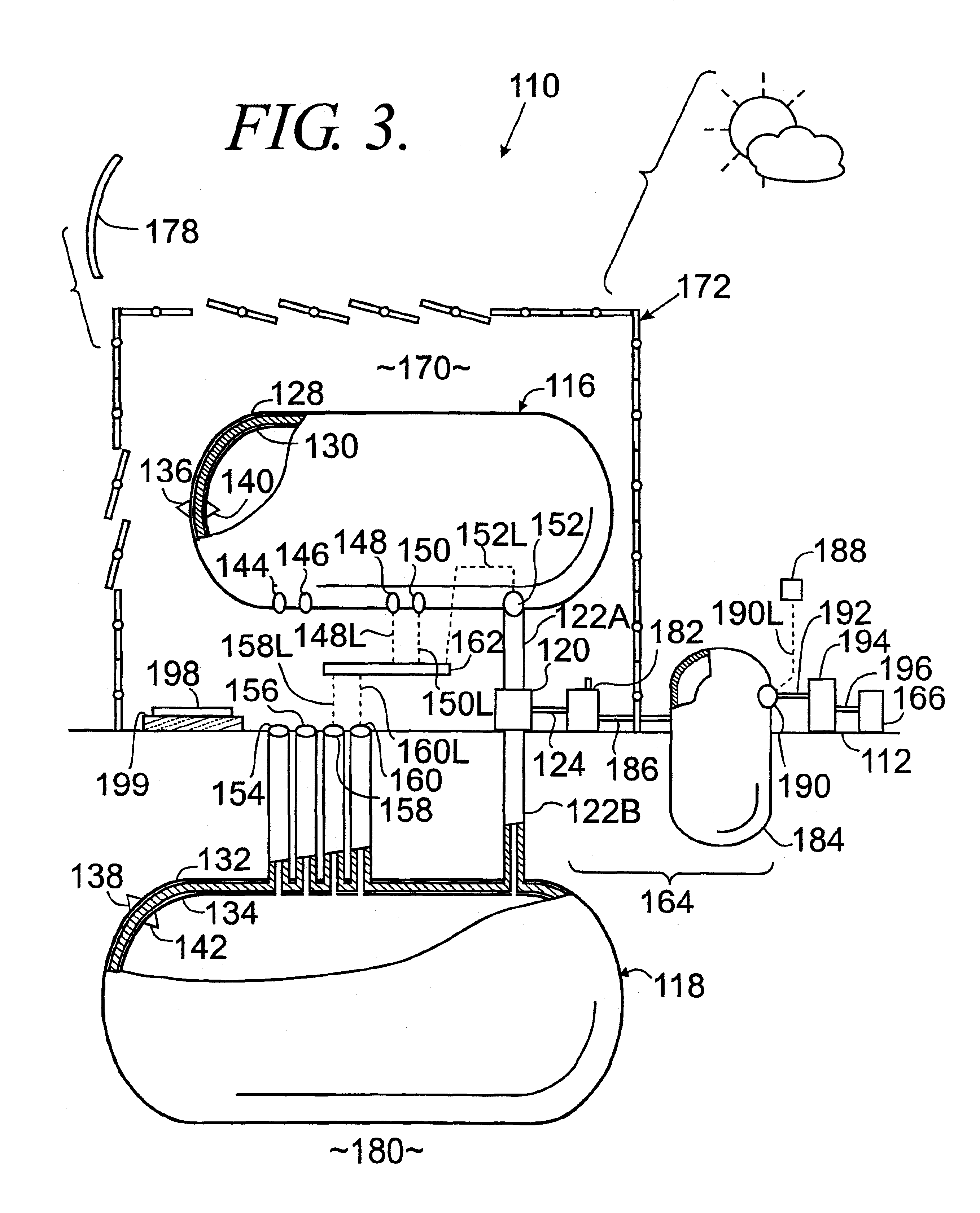
[0029]Referring initially to FIG. 1, the pressure differential compressed fluid exchanger according to a preferred embodiment of the present invention is designated generally by the numeral 10. The grade level of the earth is designated by the numeral 12. The preferred embodiment of the pressure differential compressed fluid exchanger 10 includes two containers that are each partitioned sections of a tank 14. More particularly, pressure differential compressed fluid exchanger 10 comprises a first container 16, a second container 18, and a motive power source coupled with the first container 16 by a first fluid coupler 22A and with the second container 18 by a second fluid coupler 22B. In this embodiment, the motive power source comprises a turbine 20 and is coupled with a turbine shaft 24. The first container 16 comprises an airtight section of the tank 14 adapted to contain pressurized fluid. Similarly, the second container 18 comprises a remaining airtight section of tank 14 and i...


PUM


Abstract

A method and apparatus for producing energy is provided for generating renewable energy. Captive compressed fluid cycles between two coupled containers through a motive power source. The captive compressed fluid flows between the containers in response to a difference in the pressure of the compressed fluid within the first container compared to the pressure of the compressed fluid within the second container. This pressure differential develops as the compressed fluid within the first container experiences a temperature change of a differing percentage magnitude or direction than the compressed fluid within the second container over the same period of time. The differing percentage temperature fluctuations result as the containers are provided dissimilar exposure to natural renewable or man-made energy sources or are insulated therefrom. A continuous supply of additional compressed fluid is not required, nor is fluid routinely vented to the atmosphere.

Description

CROSS-REFERENCE TO RELATED APPLICATIONS[0001]Not applicableSTATEMENT REGARDING FEDERALLY SPONSORED RESEARCH OR DEVELOPMENT[0002]Not applicableTECHNICAL FIELD[0003]This invention relates to the generation of energy.BACKGROUND OF THE INVENTION[0004]This invention relates to a method and apparatus for producing motive power and, more particularly, to a method and apparatus for generating renewable energy as captive compressed fluid cycles between two coupled containers through a motive power source. The captive compressed fluid flows between the containers in response to a difference in the pressure of the compressed fluid within the first container compared to the pressure of the compressed fluid within the second container. This pressure differential develops as the compressed fluid within the first container experiences a temperature change of a differing percentage magnitude or direction than the compressed fluid within the second container over the same period of time. The differi...

Claims


Application Information

Patent Timeline
Patent Type & Authority Patents(United States)
IPC IPC(8): F03G6/00
CPCF03G6/00Y02E10/46
Inventor CORCORAN, CRAIG C.
Owner CORCORAN CRAIG C
Learn More