
Bending method and device therefore

a bending method and a technology of a bending device, applied in the direction of metal-working devices, metal-working devices, manufacturing tools, etc., can solve the problems of troublesome input operation and input, troublesome input input, and inability to accurately bending the angle, so as to avoid manual input mistakes and high-accuracy bending angles

Inactive Publication Date: 2005-11-01
AMADA CO LTD
View PDF25 Cites 17 Cited by
  • Summary
  • Abstract
  • Description
  • Claims
  • Application Information

AI Technical Summary

Benefits of technology

[0019]Therefore, before starting the bending, since the two rotors retreat below the upper surfaces of the divided dies, when the workpiece is carried onto the die, interference between the workpiece and the rotors can be avoided.
[0045]Therefore, the function here is similar to that of the second aspect, and the positions of the plural bending angle detecting devices arranged suitably in the longitudinal direction of the die holder are detected easily by simple manual input in such a manner that the resistance line and the electric wire are externally pushed so as to come in contact with each other the time conventionally required for reading and manually inputting the positions of the bending angle detecting devices through the operator is omitted and a mistake of manual input is also avoided. Further, since the bending angle of the workpiece is detected at real time by the bending angle detecting devices, the bending state of the workpiece is detected at real time during the bending, and the gap between the punches and the die is adjusted easily, thereby obtaining the workpiece with highly accurate bending angle.

Problems solved by technology

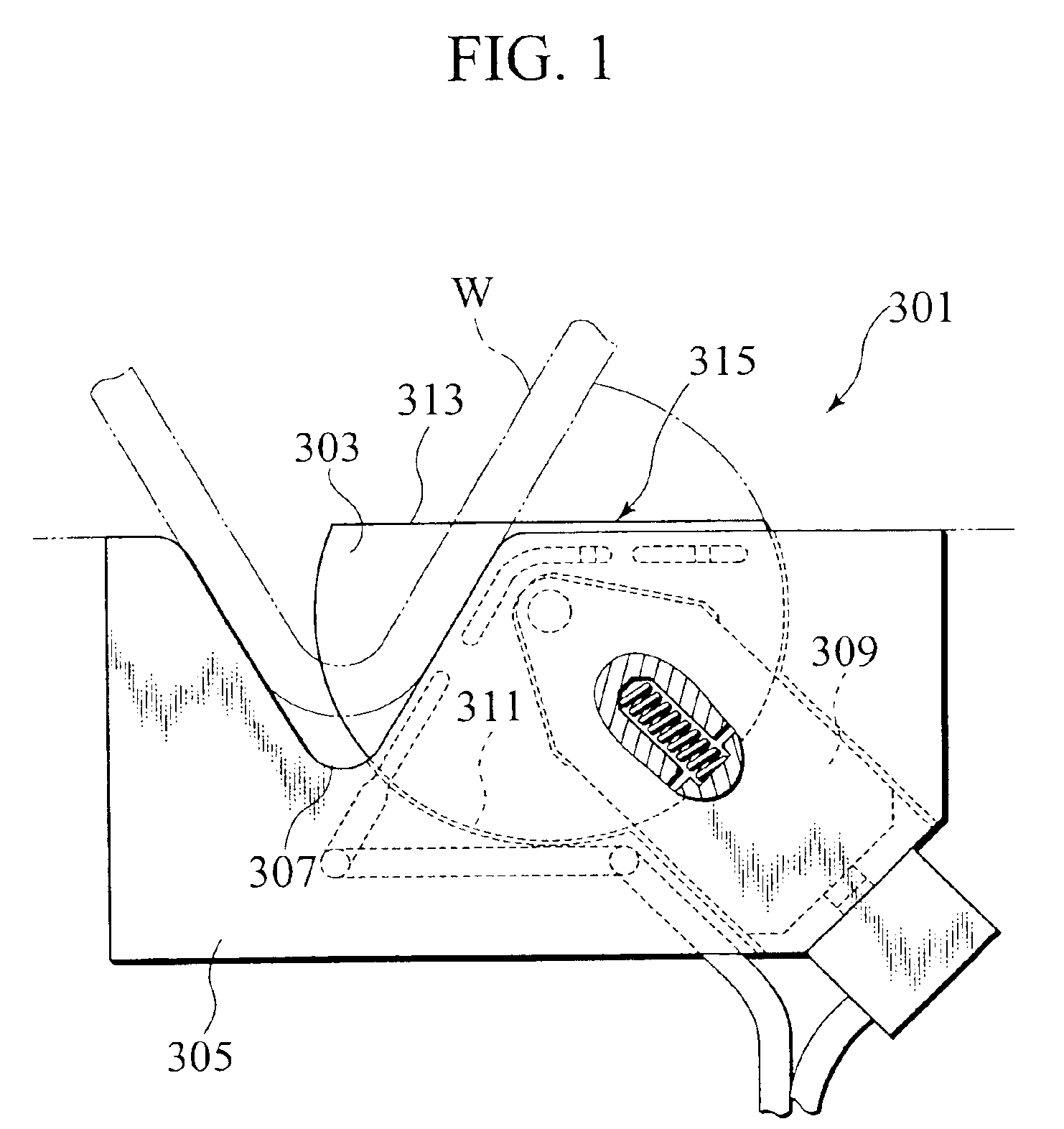
Further, since the measuring disk 303 extends upward from the upper surface of the die 305, when the workpiece W is carried in from the lateral direction so as to slide on the upper surface of the die 305, there arises a problem that interference between the workpiece W and the measuring disk 303 occurs.
In addition, since the measuring disks 303 operate individually so as to follow the sliding of the workpiece W, there arises a problem that its bending angle detecting portion becomes complicated.
Meanwhile, another conventional art has the following problem.
For this reason, there arises a problem that of troublesome input operation and misinput.
Here, since the angle sensor is provided in, for example, three places maximally, the above operation should be repeated three times, and thus this is a troublesome operation for the operator.
In the latter art, although the angle sensor is moved automatically by the control device, in the case where a bending angle cannot be measured because a hole or the like exists in the automatically determined place, there arises a problem that the position of the angle sensor should be input by using the ten key and the provided position of the angle sensor should be adjusted.

Method used


Image

  • Bending method and device therefore
  • Bending method and device therefore
  • Bending method and device therefore

Examples


first embodiment

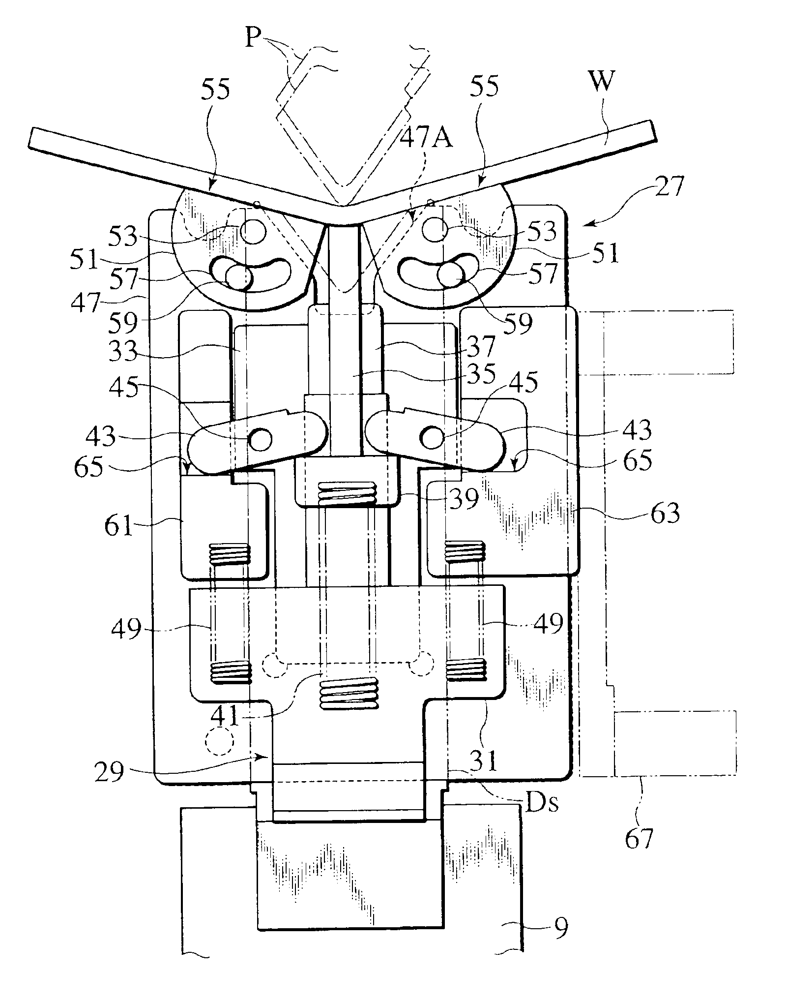
[0073]With reference to FIGS. 3 and 5, the bending angle detecting device 27 of the first embodiment composing a main section of the present invention is provided with a detecting device main body 29 at the gap between the adjacent divided dies Ds detachably, and a base portion 31 at the lower portion of the detecting device main body 29 can be attached and detached to / from the die holder 9, and, for example, a pin shaft 35 as a lifting member which is guided by a guide section 37 is provided at an approximately center of a supporting section 33 at the upper portion of the detecting device main body 29 so as to be movable up and down. The lower portion of the pin shaft 35 is provided with a first engagement member 39 having engagement portions protruding left and right as shown in FIG. 1, and the pin shaft 35 is normally biased upward with respect to the detection device main body 29 by, for example, a first spring 41, as a first elastic body.

[0074]Here, the pin shaft 35 is arranged...

third embodiment

[0130]Thereafter, as the present invention, the bending method in the bending apparatus and the apparatus thereof will be explained below with reference to the drawings by exemplifying the hydraulic press brake as the press brake.

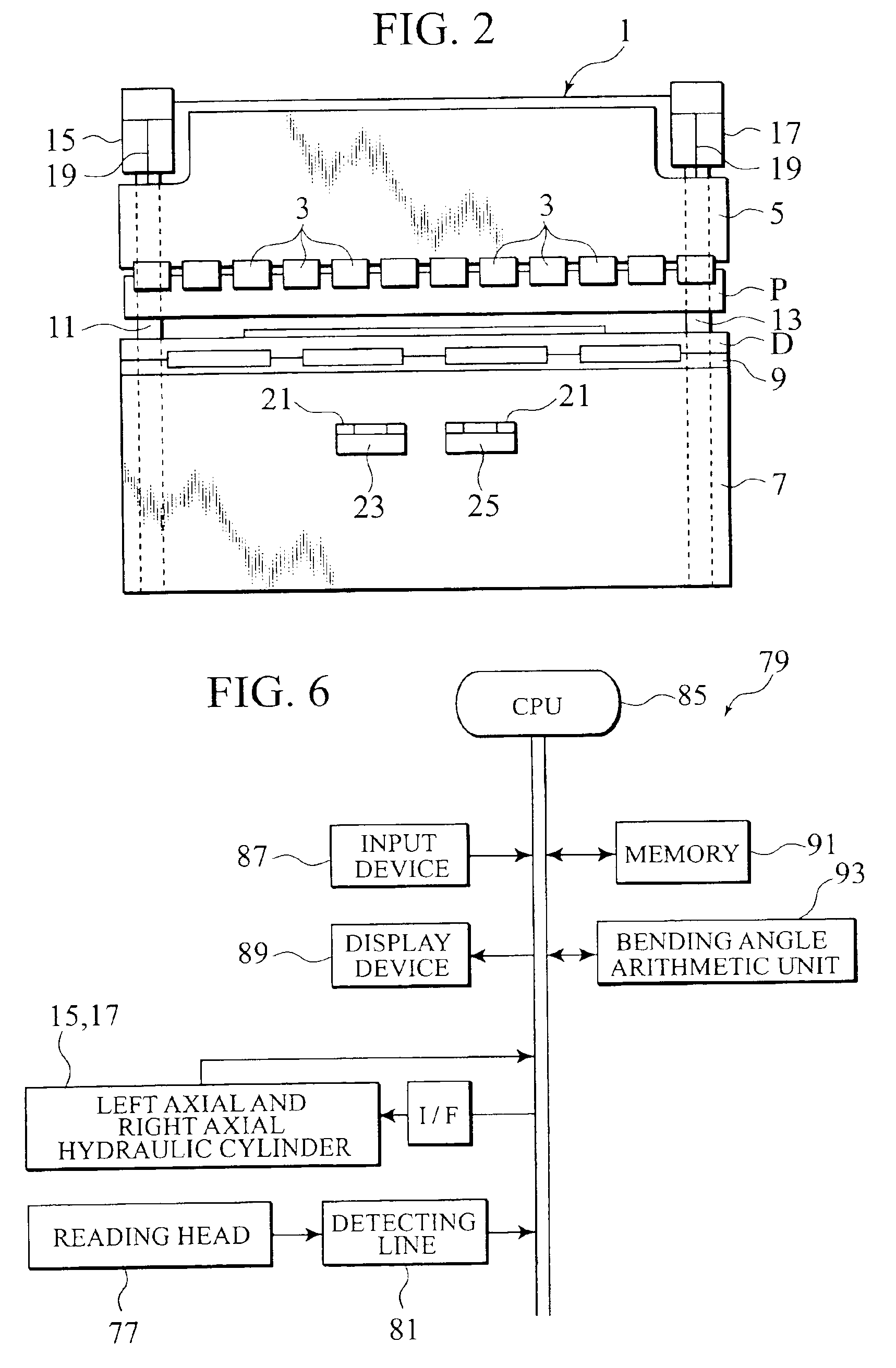
[0131]With reference to FIGS. 2 and 12, a press brake 201 of the present embodiment refers to the lowering type hydraulic press brake, but a lifting type press brake or a mechanical press brake such as crank which is not of the hydraulic type may be used.

[0132]The lowering type hydraulic press brake 1 is mounted and fixed to the lower surface of, for example, the upper table 5 as a movable table movable up and down, namely a ram, via a plurality of intermediate plates 3 where the punches P are arrange with equal intervals. The die D is mounted and fixed to the upper surface of, for example, the lower table 7 as a fixed table via a die holder 9. Therefore, the upper table 5 lowers and the workpiece W as a plate material is bent between the punches P and the ...


PUM

PropertyMeasurementUnit
Timeaaaaaaaaaa
Forceaaaaaaaaaa
Angleaaaaaaaaaa

Abstract

A bending apparatus reciprocates at least one of an upper table to which a punch is mounted and a lower table to which a corresponding plurality of adjacent divided dies are mounted. At least one bending angle detector is provided between the dies to detect a bending angle of the workpiece. A main body inserts the bending angle detector into a gap between the dies and withdraws the bending angle detector from the gap between the dies. A lift is biased upward by a first elastic body and is configured to be pressed downward by the workpiece at approximately a center of a groove portion of the dies. The lift includes a first engagement member. A rotor support is biased upward by two second elastic bodies having smaller biasing forces than the first elastic body. The rotor support includes second engagement members. Two rotors are provided on opposite sides of the groove portion at an upper portion of the rotor support. The two rotors include workpiece contacts that contact the workpiece. Links rotatably engage the first engagement member to stop an upper end of the lift in a position lower than an upper surface of the dies, and rotatably engage the second engagement members to position the workpiece contacts below the upper surface of the dies. A bending angle calculator converts rotating amounts of the two rotors into bending angles of the workpiece.

Description

TECHNICAL FIELD[0001]The present invention relates to a bending method in a bending apparatus such as a press brake and an apparatus thereof, and particularly relates to the bending method in a bending apparatus having an angle detecting device for detecting a bending angle of a bent workpiece and the apparatus thereof.BACKGROUND ART[0002]Conventionally, a press brake is used a lot for bending a plate-shaped workpiece, and when a worked product is manufactured, the bending which provides highly accurate bending angle and flange dimension of a workpiece is strongly desired. For this reason, a bending apparatus which has an angle detecting device for measuring a bending angle of a workpiece instantly and accurately is required.[0003]The above-mentioned angle detecting device 301 is disclosed in Japanese Patent Application Laid-Open No. 6-238343 (1994), and it is, as shown in FIG. 1, provided with a measuring disk 303 having a shape of a flat semicircular disk whose measuring member ha...

Claims


Application Information

Patent Timeline
IPC IPC(8): B21D5/02
CPCB21D5/02B21D5/0209B21D5/042Y10S72/702B21D5/0272
Inventor MATSUMOTO, MASATERUYANAGAWA, KOICHIHATANO, KENTAKIZAWA, YUTAKA
Owner AMADA CO LTD
Learn More