
Injection device capable of injecting liquid

An injection device and liquid technology, applied in the directions of syringes, automatic injectors, hypodermic injection devices, etc., can solve the problems of affecting the normal flow of tracheal gas, easy deformation of the trachea, deviation of injection volume, etc., so as to avoid the risk of manual input errors and reduce the The probability of squeezing the trachea, the effect of simple appearance

Inactive Publication Date: 2022-08-05
深圳市普朗医疗科技发展有限公司
View PDF0 Cites 0 Cited by
  • Summary
  • Abstract
  • Description
  • Claims
  • Application Information

AI Technical Summary

Problems solved by technology

[0002] Water light gun is a kind of non-surgical injection beauty anti-ageing technique that is popular all over the world. Through the magic anti-aging gun, water light needle and other beauty liquids need water light gun For the injection device to inject, when the existing injection device installs the water light needle on the water light gun, it is necessary to manually input the specifications of the syringe, so that the accurate injection can be performed. This method has certain potential safety hazards. Once the manual input is wrong, Will lead to deviations in the injection volume and affect the safety of the injected person
And every time the syringe is replaced, it is necessary to carefully check the specifications of the syringe manually and enter it correctly, which is time-consuming and laborious. At the same time, the air pipe of the existing injection device is external, and the staff will inevitably squeeze when operating the water light needle. At this time, the trachea is easily deformed, which will affect the normal circulation of gas inside the trachea

Method used


Image

  • Injection device capable of injecting liquid
  • Injection device capable of injecting liquid
  • Injection device capable of injecting liquid

Examples


Embodiment Construction

[0028] The technical solutions in the embodiments of the present invention will be clearly and completely described below with reference to the accompanying drawings in the embodiments of the present invention. Obviously, the described embodiments are only a part of the embodiments of the present invention, but not all of the embodiments. Based on the embodiments of the present invention, all other embodiments obtained by those of ordinary skill in the art without creative efforts shall fall within the protection scope of the present invention.

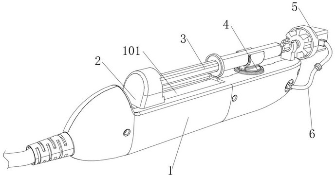
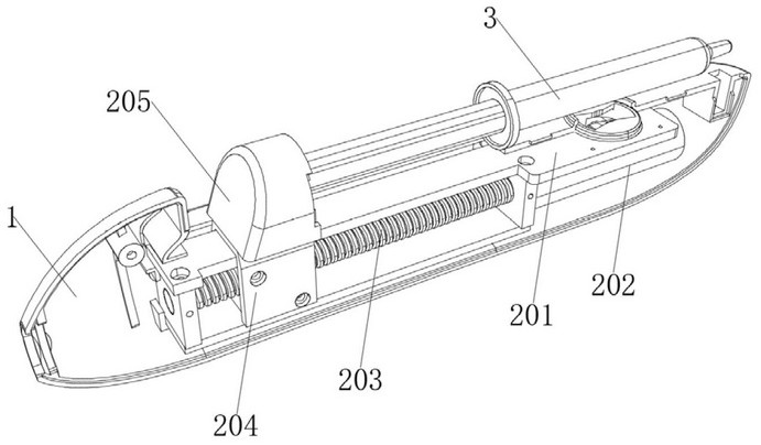
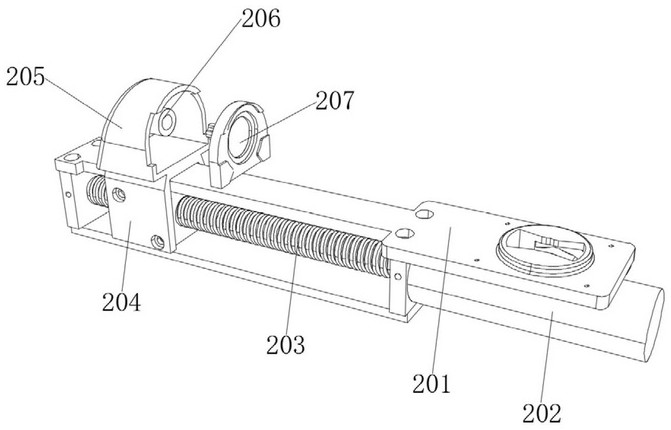
[0029] see Figure 1-9As shown, an injection device capable of injecting liquid comprises a casing 1, a water light needle 3 is arranged at the top of the casing 1, an automatic injection mechanism 2 is arranged inside the casing 1, and the top of the automatic injection mechanism 2 penetrates out of the casing The body 1 is connected with one end of the water light needle 3, a clamping identification mechanism 4 is arranged between t...


PUM


Abstract

The invention relates to the technical field of skin beautifying equipment, in particular to an injection device capable of injecting liquid, which comprises a shell, a hydro-optical needle is arranged at the top end of the shell, an automatic injection mechanism is arranged in the shell, and the top end of the automatic injection mechanism penetrates through the shell and is connected with one end of the hydro-optical needle; a clamping identification mechanism is arranged between the hydro-optical needle and the shell; the clamping recognition mechanism in the device can automatically recognize the specification of the needle cylinder, the link of manually inputting the specification of the needle cylinder is avoided, the risk of manual input errors is avoided, the safety of an injection person is ensured, meanwhile, medical accidents are reduced, time and labor are saved, and compared with an air pipe directly arranged outside the shell, the device is more convenient to use. The probability that a worker extrudes the air pipe can be reduced, normal circulation of the air pipe is guaranteed, the situation that when a traditional air pipe needs to change the airflow direction, the air pipe is bent by 90 degrees, and an air channel is easily blocked is avoided, and blocking is effectively reduced.

Description

technical field [0001] The invention relates to a water light gun, in particular to an injection device capable of injecting liquid, and belongs to the technical field of skin beauty equipment. Background technique [0002] The water light gun is a non-surgical injection beauty anti-aging technique that is popular in the world. Through the magic anti-aging gun, the water light needle and other beauty liquids need to be injected with the water light gun as the injection device. The existing injection device injects the water light needle. When it is installed on the water light gun, it is necessary to manually input the specifications of the syringe, so that accurate injection can be carried out. This method has certain safety hazards. Once the manual input is wrong, it will lead to deviation of the injection volume and affect the safety of the injected person. And every time the syringe is replaced, it is necessary to manually check the specifications of the syringe carefull...

Claims


Application Information

Patent Timeline
Patent Type & Authority Applications(China)
IPC IPC(8): A61M5/20A61M5/31A61M5/315
CPCA61M5/20A61M5/2053A61M5/31A61M5/3129A61M5/315A61M5/31511A61M2005/3142A61M2005/2006A61M2205/6018A61M2205/6027A61M2205/60Y02E60/10
Inventor 温瑞环张良吴达文海
Owner 深圳市普朗医疗科技发展有限公司
Learn More