
Steering triangle

Inactive Publication Date: 2005-11-01
ZF FRIEDRICHSHAFEN AG
View PDF12 Cites 89 Cited by
  • Summary
  • Abstract
  • Description
  • Claims
  • Application Information

AI Technical Summary

Benefits of technology

[0008]Another advantage of the present invention can be seen in the fact that due to the possibility of axial, prepressing the rubber-metal bearing can be set for different requirements, whereas the rubber blend used for the elastomer body may have to be modified for different rigidities in conventional constructions known from the state of the art.
[0009]The pressing rings are preferably rigidly connected to the customer body, and this rigid connection may be embodied, e.g., by vulcanization / molding-on. The proceccing in the axial direction is performed via the pressing rings.
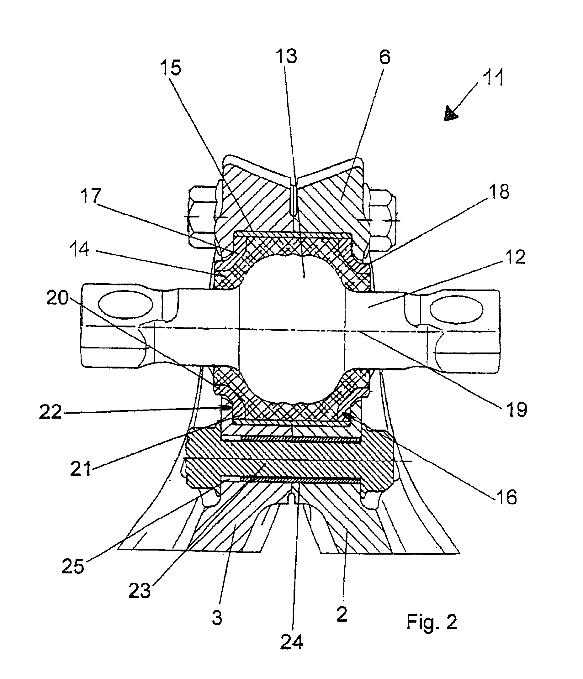
[0010]Provisions are made according to an expedient variant for the pressing device to have a plurality of pressing screw connections, which are arranged in parallel to the pivot axis and are accommodated in through holes of the joint housing. The pressing screw connections represent an inexpensive possibility of a simple design for prepressing the pressing rings by screwing together the control arms in the area of the joint housing formed jointly with the necessary forces.
[0011]Sufficient pressing forces are provided here, e.g., by three or more pressing screw connections arranged coaxially around the central recess for the rubber-metal bearing.
[0012]To reduce the shearing forces appearing in the area of the central joint housing connection especially in the case of very great torsions of the two control arms in relation to one another and not to overload the pressing screw connections located there, it proved, moreover, to be advantageous to provide at least one of the pressing screw connections with a shearing sleeve, which is arranged within the through hole associated with the said pressing screw connection and extends around the tensioning screw.
[0013]However, it is also possible to provide all pressing screw connections with shearing sleeves which are arranged within the through holes and extend around the pressing screws.

Problems solved by technology

However, the drawback of such control arms is that the rubber-metal bearing arranged within the central joint housing formed by the two control arms together provides for the pretension of the elastomer body responsible for the elastic mounting in the radial direction only due to its design.

Method used


Image

  • Steering triangle
  • Steering triangle
  • Steering triangle

Examples


Embodiment Construction

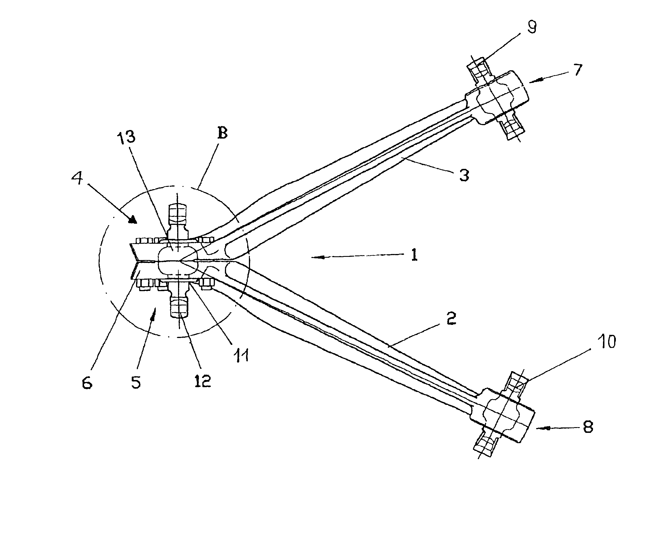
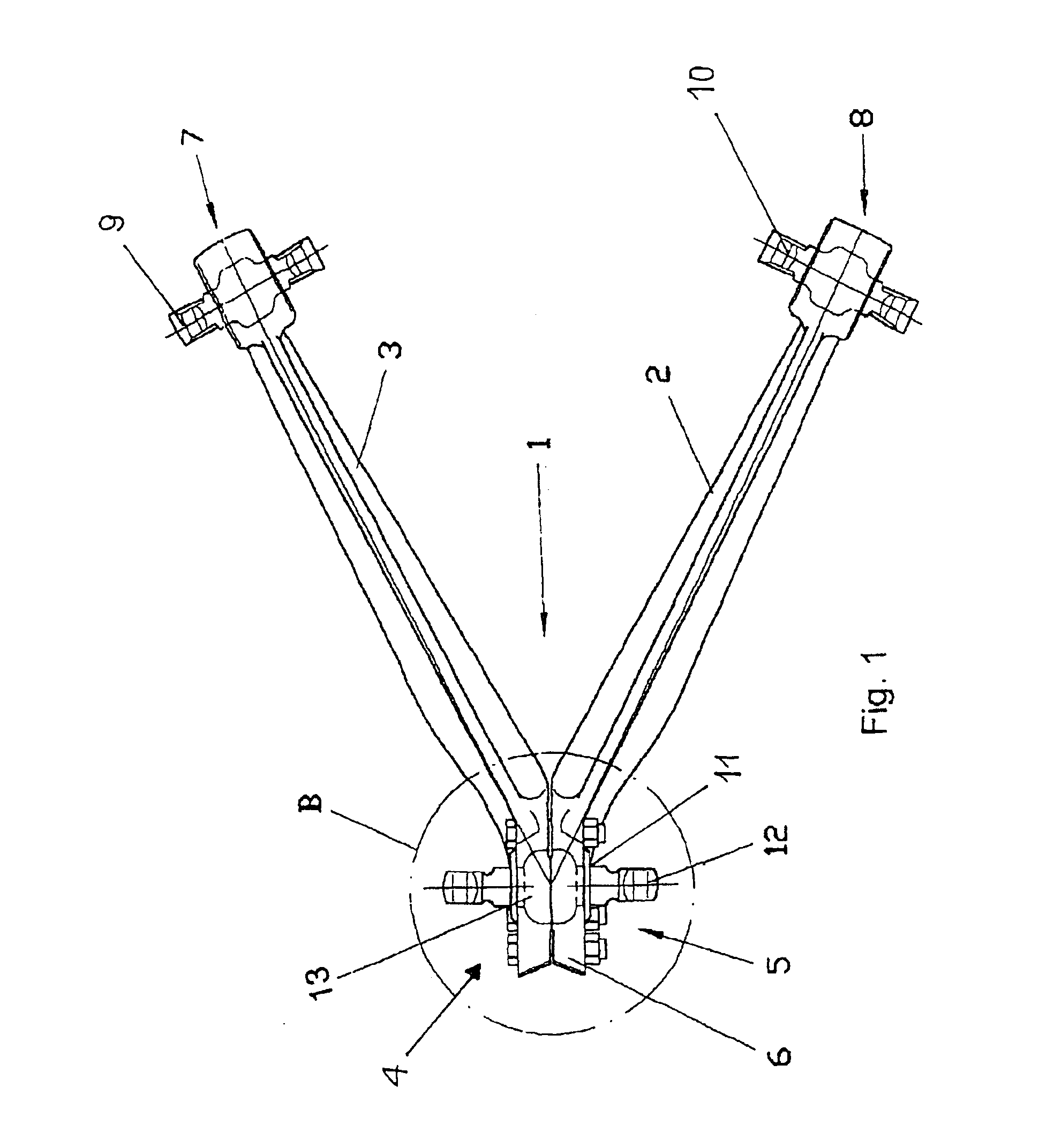
[0017]Referring to the drawings in particular, the steering triangle is designated in its entirety by 1 and is shown in FIG. 1. The steering triangle 1 has two control arms 2 and 3, which are mirror-symmetrical to each other. The control arm 2 has an end area 5 bent at an angle. The control arm 3 has an end area 4 bent at an angle. The two end areas 4 and 5 together form the joint housing 6. Due to the end areas 4 and 5 being bent at angles and the contact surfaces of the control arms 2 and 3 located in this area, the entire steering triangle 1 has an essentially V-shaped form when viewed in the horizontal projection. The steering triangle 1 has two end areas 7 and 8, which are used for fastening the steering triangle 1 to body-side mounts, which are not specifically shown here. The steering triangle 1 is fastened in an articulated manner by means of rubber-metal bearings 9 and 10. A rubber-metal bearing 11 establishes an articulated connection with a utility vehicle axle, which is ...


PUM


Abstract

A steering triangle (1) is provided for the axle suspension of motor vehicles for the articulated connection of a vehicle axle with a vehicle chassis with two control arms (2, 3). The control arms are connected to each other in a joint housing (6) formed by the control arms (2, 3) together for a rubber-metal bearing (11) for fixing the steering triangle (1) on the vehicle axle. The rubber-metal bearing (11) has a pivot axis (12) provided with a spherical surface and an elastomer body (14), which extends around the pivot axis (12) at least in the area of the spherical surface and which is accommodated in a recess (16) located within the joint housing (6), in which steering triangle two pressing rings (17, 18) are arranged within the recess (16) of the joint housing (6) on the axial outer sides of the elastomer body (14). The pressing rings can be moved toward each other by a tensioning device via the intermediary of stop faces (22) of the joint housing (6). The stop faces are in contact with the outer sides of the pressing rings (17, 18), which outer sides face away from each other. The rubber-metal bearing can be pretensioned both in the axial direction and in the radial direction, so that stronger forces can be absorbed due to the higher rigidity achieved as a result.

Description

CROSS REFERENCE TO RELATED APPLICATION[0001]This is a continuation of and claims the benefit (35 U.S.C. §120 and 365(c)) of copending International Application PCT / DE 03 / 00418 of Feb. 12, 2003, which designated inter alia the United States and which claims the priority of German Application DE 102 19 708.3 of May 2, 2002. The entire contents of each application is hereby incorporated by reference in its entirety.FIELD OF THE INVENTION[0002]The present invention pertains to a steering triangle for the axle suspension of motor vehicles for the articulated connection of a vehicle axle with the vehicle chassis with two control arms, which are connected to each other in a joint housing formed together by the said control arms.BACKGROUND OF THE INVENTION[0003]Such steering triangles, which have been known from the state of the art, are used especially in utility vehicles. Thus, for example, a control arm for a motor vehicle wheel suspension has been known, which comprises a two-part arm b...

Claims


Application Information

Patent Timeline
IPC IPC(8): B60G7/00F16F1/38F16F1/393F16C11/06B60G1/00B60G7/02F16F15/08
CPCB60G7/001B60G7/005F16C11/0614F16F1/393B60G2200/315B60G2204/143B60G2204/148Y10T403/32737B60G2206/124B60G2206/91B60G2204/416F16C2326/05F16C11/083
Inventor BUHL, REINHARDRICHTER, REINHARDCOSSMANN, UWEKUNZE, RALFBUBLIES, HOLGERKNOPP, SOREN
Owner ZF FRIEDRICHSHAFEN AG
Learn More