Backlight apparatus, and a liquid crystal display (LCD) therewith

Inactive Publication Date: 2005-11-01
SHARP KK
View PDF22 Cites 33 Cited by
  • Summary
  • Abstract
  • Description
  • Claims
  • Application Information

AI Technical Summary

Benefits of technology

[0016]To achieve these and other advantages and in accordance with the purpose of the invention, as embodied and broadly described-herein, the invention provides, among other means, a proximity section in a holder that holds the luminescent sources, which helps improve heat conductivity for a center part where the luminescent sources are close together, and the temperature is the highest. The proximity section that is close to the luminescent sources has a space on its back side that is used to lay wiring, resulting in space saving. Where there are three or more luminescent sources, one or two centrally positioned luminescent sources that tend to be the hottest are placed closer to the holder than other luminescent sources, such that heat-dissipation of the centrally positioned luminescent sources is enhanced, resulting in an improvement of overall heat dissipation efficiency. Since the temperature of two electrode sections toward the ends of each of the luminescent sources tends to be the highest, the distance between the luminescent source and the holder in the longitudinal direction of the luminescent source is made such that the distan

Problems solved by technology

The proximity section that is close to the luminescent sources has a spac

Method used


Image

  • Backlight apparatus, and a liquid crystal display (LCD) therewith
  • Backlight apparatus, and a liquid crystal display (LCD) therewith
  • Backlight apparatus, and a liquid crystal display (LCD) therewith

Examples


second embodiment

[0059]Next, the present invention is explained.

[0060]FIG. 7 shows a backlight apparatus 20B, and an LCD 21B using the backlight apparatus 20B of the second embodiment. Here, in FIG. 7, about the same components as shown in FIG. 5 and FIG. 6 in the first embodiment, the same reference numbers are attached and the explanation thereof is not repeated. This practice will apply to explanations and drawings of the third embodiment et seq., to be described later.

[0061]The proximity section 41 of the backlight apparatus 20B of the present embodiment is formed in a middle position of the pair of fluorescent light bulbs 23, like the first embodiment, where the temperature becomes the highest in the fluorescent light bulb assembly 40B. The second embodiment is characterized by providing the wiring 33 of the fluorescent light bulb 23 on a side of the proximity section 41 other than the side to which the fluorescent light bulb 23 faces. This position will be hereafter called the backside.

[0062]A...

third embodiment

[0065]Next, the present invention is explained.

[0066]FIG. 8 shows a backlight apparatus 20C, and an LCD 21C using the backlight apparatus 20C of the third embodiment of the present invention.

[0067]The backlight apparatus 20C of the third embodiment includes three fluorescent light bulbs 23 (designated 23A, 23B, and 23C), in order to attain high brightness. As shown in FIG. 8, the fluorescent light bulb 23B is provided in the middle of the three fluorescent light bulbs 23A, 23B, and 23C. The present embodiment is characterized by having arranged the fluorescent light bulb 23B closer to the holder 27 than the other fluorescent light bulbs 23A and 23C. Positions of the fluorescent light bulbs 23A, 23B, and 23C can be relatively easily determined by arranging supporting holes for the fluorescent light bulbs 23A, 23B, and 23C, which are formed on the holder 27.

[0068]By the way, when three or more fluorescent light bulbs are provided, the fluorescent light bulb located in the middle has t...

fourth embodiment

[0071]Next, the present invention is explained.

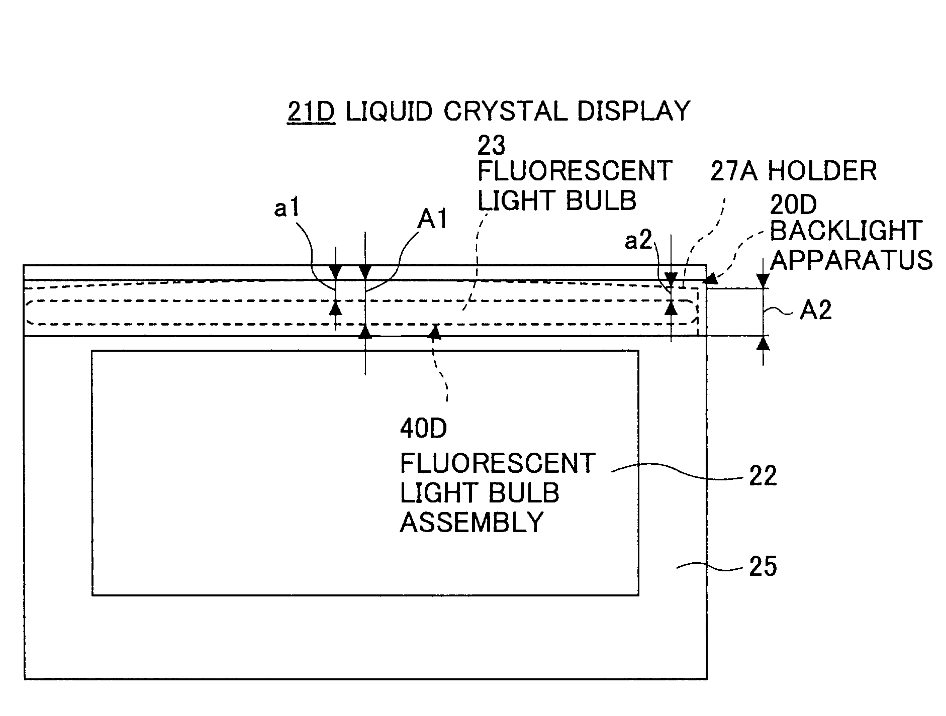
[0072]FIG. 9 shows a backlight apparatus 20D, and an LCD 21D using the backlight apparatus 20D of the fourth embodiment. The present embodiment is characterized by a tapering shape of the space between the holder 27A and the fluorescent light bulb 23, which are included in the fluorescent light bulb assembly 40D. The space is the widest at the center of the fluorescent light bulb 23, and decreases in width toward each end (henceforth both end positions) of the fluorescent light bulb 23, where the electrode section 31 is formed.

[0073]Specifically, since the diameter size of the fluorescent light bulb 23 is uniform over its longitudinal direction, the holder 27 is structured such that the space at the both-end positions is set small (A2 in FIG. 9), while the space at the center is set large (A1 in FIG. 9). By employing this structure, the space between the fluorescent light bulb 23 and holder 27A at the both-end positions is set at a2, an...


PUM


Abstract

Dissipation of heat generated by a luminescent source, such as a fluorescent lamp, of a backlight apparatus and an LCD therewith is enhanced by providing a proximity section in a holder, making the hottest part the closest to the holder for efficient heat conduction.

Description

BACKGROUND OF THE INVENTION[0001]1. Field of the Invention[0002]The present invention generally relates to a backlight apparatus, and a liquid crystal display (LCD), and especially relates to a backlight apparatus including a luminescent source that generates heat, such as a fluorescent lamp, and an LCD that employs the backlight apparatus.[0003]Conventionally, CRT (cathode-ray tube) displays have been used. In recent years, use of thin displays that employ an LCD panel has been progressing. Display quality of the LCD has been enhanced, and enlargement and higher brightness of the displays are desired for television use, etc. With requirements of brighter LCDs increasing, demands are increasing for a backlight apparatus that can provide the illumination for the enlarged and brighter liquid crystal panel.[0004]2. Description of the Related Art[0005]Conventional LCDs have been used mainly by notebook PCs, when up to about 13 inch displays are the main thrust with a screen brightness o...

Claims


Application Information

Patent Timeline
IPC IPC(8): F21V8/00G02F1/1335G02F1/13F21V29/00G02F1/1333F21V29/15F21Y103/00G02F1/13357
CPCG02B6/0068G02B6/0071G02B6/0085G02F1/133615G02B6/0031G02B6/0083G02B6/009G02F1/1335
Inventor NITTO, EIJIYONEMURA, KOSHUTAKAHASHI, HIROYOSHIHAYASHIMOTO, SEIJIMIYAMOTO, HIROFUMI
Owner SHARP KK
Why Eureka
Try Eureka