Image positioning method and system for tomosynthesis in a digital X-ray radiography system

a radiography system and image positioning technology, applied in the field of tomosynthesis, can solve the problems of not having depth information, not knowing with great precision, and difficult to move the x-ray source to multiple positions with the requisite degree of precision, so as to improve the image quality of the resulting synthesized imag

Inactive Publication Date: 2005-11-01
ANLOGIC CORP (US)
View PDF16 Cites 40 Cited by
  • Summary
  • Abstract
  • Description
  • Claims
  • Application Information

AI Technical Summary

Benefits of technology

[0015]The x-ray source may be moved in both the x- and y-directions within the lateral plane, in order to improve the image quality of the resulting synthesized image. In this case, multiple markers are used, in order to detect the shifts in both the x- and y-directions. Markers may also be used in a tomography system having a rotating x-ray source, in order to detect the rotation angle of the x-ray source.

Problems solved by technology

There is no depth information, however, in the images obtained by stationary two-dimensional arrays of digital detectors, unlike in the images obtained by CT scanning.
One of the drawbacks of digital tomosynthesis is that the relative location of the x-ray source with respect to the detector array must be known with great precision, as the x-ray source is being moved with respect to the object being imaged.
It is difficult, however, to move the x-ray source to multiple positions with the requisite degree of precision.
Uncertainties in the position of the x-ray source and / or the x-ray detector generally contribute to image blurring.

Method used


Image

  • Image positioning method and system for tomosynthesis in a digital X-ray radiography system
  • Image positioning method and system for tomosynthesis in a digital X-ray radiography system
  • Image positioning method and system for tomosynthesis in a digital X-ray radiography system

Examples


Embodiment Construction

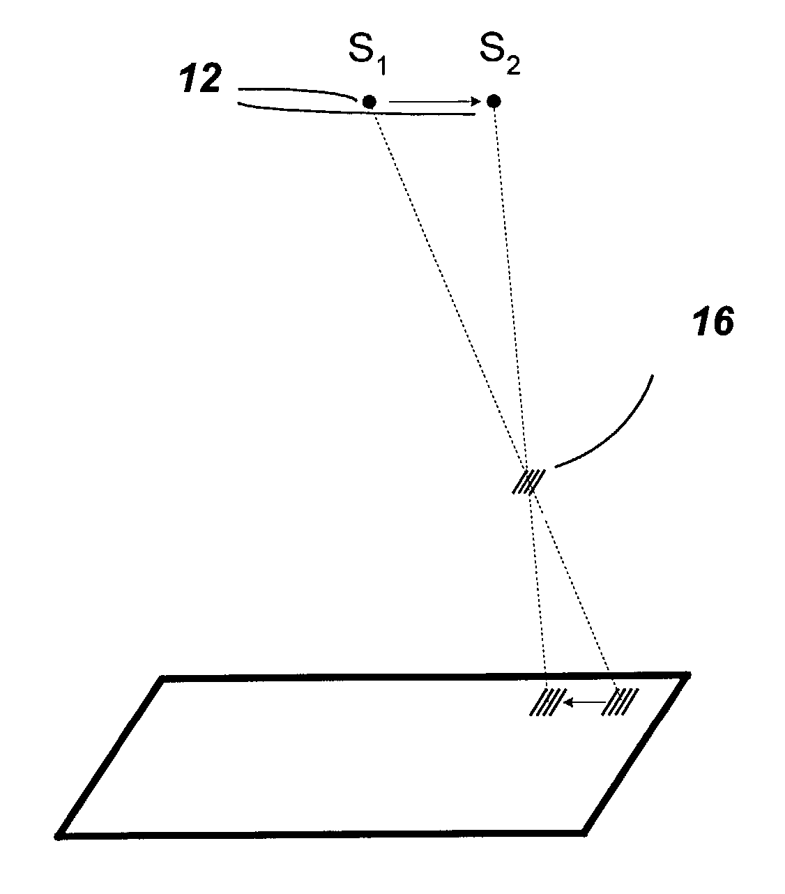
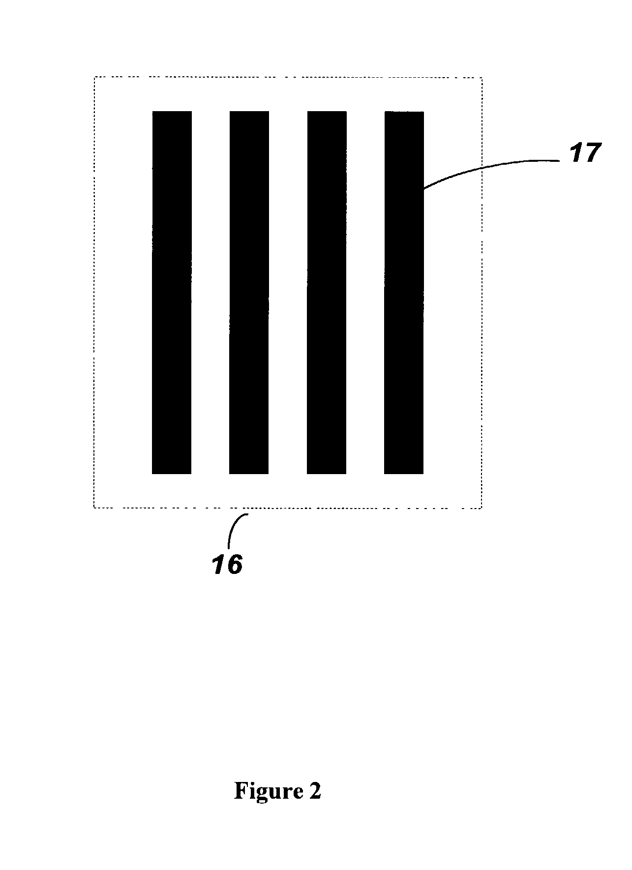
[0024]The present invention features a method and system for aligning the two-dimensional image data in a digital tomosynthesis system. In the present invention, the shift required for each 2-D image used in digital tomosynthesis to synthesize or reconstruct a 3-D image is calculated, using the image of one or more markers having a specifically designed pattern.

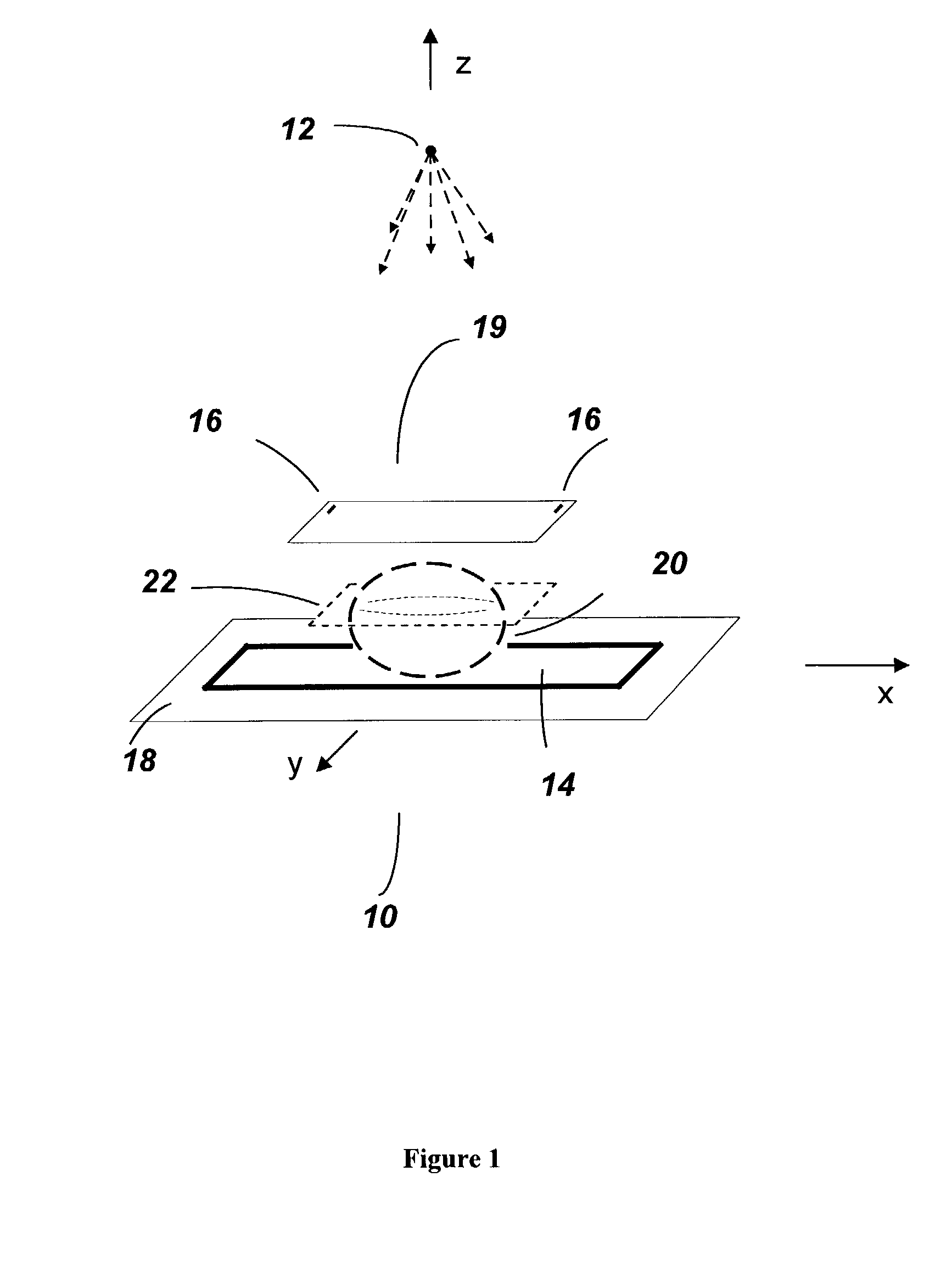
[0025]FIG. 1 schematically illustrates a digital tomosynthesis system 10, constructed in accordance with one embodiment of the present invention. In overview, the system 10 includes a radiation source 12, a radiation detector system 14, and at least one marker 16 disposed between the radiation source 12 and the radiation detector system 14. Preferably, the radiation source is an x-ray source 12, and the radiation detector system is a planar digital x-ray detector system 14 lying in a detector plane 18. The x-ray source 12 generates x-rays that are transmitted through a target object 20 that is being imaged. The target object ...


PUM

PropertyMeasurementUnit
distanceaaaaaaaaaa
phase shiftaaaaaaaaaa
displacementaaaaaaaaaa

Abstract

The present invention provides a method and system for determining the position of the image of a target object or the position of the x-ray source in digital tomosynthesis, as the x-ray source is moved relative to the object so as to obtain multiple two-dimensional images of the object from multiple angles. At least one marker, characterized by a simple and known image pattern, is disposed between an x-ray source and a detector system. The shift in the image of the object, resulting from the movement of the x-ray source during tomosynthesis, is calculated to a desired resolution using the readily observable shift in the image of the marker. The x-ray source may be translated along a plane parallel to the plane of the detector system, or may be rotated about a fixed center.

Description

CROSS REFERENCES TO RELATED APPLICATIONS[0001]This application claims the benefit of priority under 35 U.S.C. §119(e) from co-pending, commonly owned U.S. provisional patent application Ser. No. 60 / 316,511, entitled “A Digital X-Ray Radiography System For Tomosynthesis,” filed on Aug. 31, 2001.STATEMENT OF GOVERNMENT INTEREST[0002]The U.S. Government has no interest in or to this patent.FIELD OF THE INVENTION[0003]The present invention relates generally to tomosynthesis, and more particularly to an image positioning method and system for digital tomosynthesis.BACKGROUND[0004]Standard x-ray radiography allows an x-ray image of a target object to be obtained, by capturing x-rays transmitted through the object onto a film screen. The x-ray image is a projection of the object along the x-ray direction. In the x-ray image, variations in the composition and thickness of the target object in different regions of the object are revealed, as a result of their differential absorption of the x...

Claims


Application Information

Patent Timeline
Patent Type & Authority Patents(United States)
IPC IPC(8): A61B6/02G01N23/02G01N23/04
CPCA61B6/025G01N23/046G01N2223/419G01N23/044
Inventor LAI, CHING-MING
Owner ANLOGIC CORP (US)
Why Eureka
Try Eureka