Orthopedic leg brace

Inactive Publication Date: 2005-11-01
NASA
View PDF16 Cites 24 Cited by
  • Summary
  • Abstract
  • Description
  • Claims
  • Application Information

AI Technical Summary

Benefits of technology

[0009]Still another object is to provide a knee brace which will lock in any position because its locking mechanism functions in small increments.
[0010]Existing knee brace locking devices have been either cone clutches, roller type clutches or single pawl ratchet devices. Variations in friction due to clutch surface conditions, as well as the distance pawls must normally travel before engaging or locking, can lead to a knee joint which gives way. My issued patent, U.S. Pat. No. 5,490,831 overcame many of these disadvantages, but as noted in the prior art, there is still room for improvement. This invention embraces a major step in that direction.
[0011]Orthopedic knee brace assemblies usually include upper and lower side braces to support a user's leg with a knee joint housing between them accommodating means for pivotal movement. The key to knee braces, then, is the knee joint housing. The knee joint housing herein is in the form of inner and outer housing members. The upper side brace is integral with the outer housing member, and the lower side brace is integral with the inner housing member. A ratchet ring having internal teeth is mounted in the outer housing member so that it rotates when the upper side brace swivels. A number of cam action pawls, with teeth adapted to engage the internal ratchet ring teeth, are mounted in the inner housing member. The cam action pawls are provided with return springs to hold the pawl teeth in engagement with the ratchet ring teeth. The inner and outer housing members are coupled together to form a knee joint hinge. Ratchets are created in the housing when the cam action pawls in the inner housing member engage the teeth inside the ratchet ring in the outer housing

Problems solved by technology

U.S. Pat. No. 4,361,142, that it is particularly difficult to provide orthopedic knee appliances which provide stability while still duplicating or accommodating the complex flexion and extension actions which a knee undergoes.
Otherwise the knee brace

Method used


Image

  • Orthopedic leg brace
  • Orthopedic leg brace
  • Orthopedic leg brace

Examples


Embodiment Construction

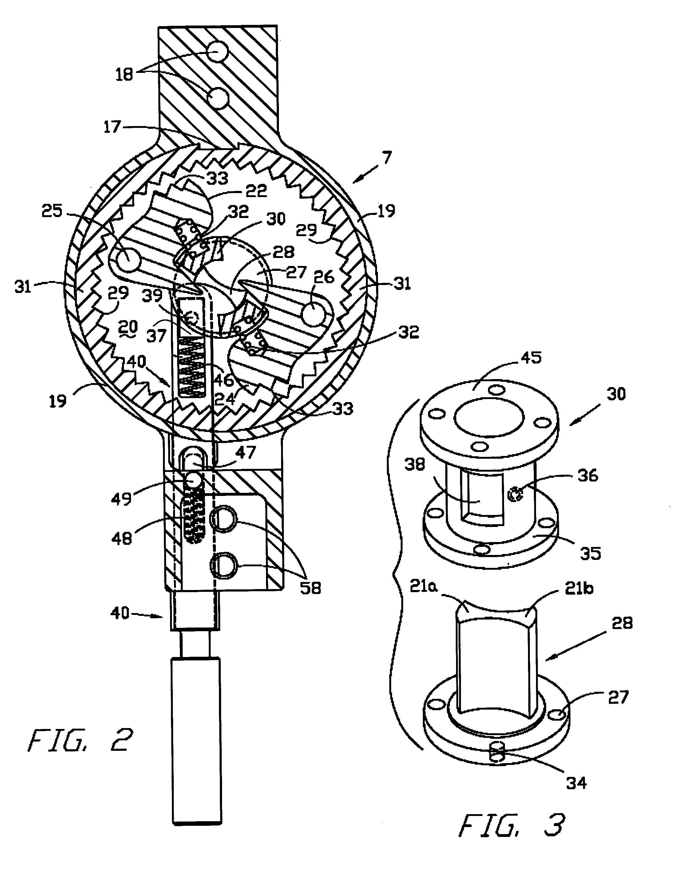
[0012]It is not known in the art that multiple pawls permit a ratchet wheel to be locked when rotated a distance much shorter than the distance it must rotate when one pawl is used in a knee brace. Two pawls are disclosed in U.S. Pat. No. 4,520,804, but they are employed to enable the user to quickly and easily alter the relative pivotal movement and positioning between upper and lower leg sections. One pawl limits clockwise rotation, and one pawl limits counterclockwise rotation. The double locking ratchet knee joint in U.S. Pat. No. 4,520,804 accomplishes this movement through the use of manually actuatable locking levers. Thus, heretofore knee braces would not lock until the pawl moved a distance of at least one full tooth, during which the user's leg was unsupported. As will be appreciated, herein the pawl can be made to move less than the distance between two teeth. For a better understanding of how this is accomplished a description of the invention in conjunction with the acc...


PUM


Abstract

Knee braces generally have been rigid in both the knee bending direction and in the knee straightening direction unless a manually operated release is incorporated in them to allow the knee to bend. Desirably a braced knee joint should effectively duplicate the compound, complex, actions of a normal knee. The key to knee braces is the knee joint housing. The housing herein carries a number of cam action pawls, with teeth adapted to engage the internal teeth of a ratchet ring mounted in the housing. Cam action return springs and the shape of the cam action pawl teeth allow rotation of the ratchet ring in a leg straightening direction while still supporting a load. The leg can then be extended during walking while at the same time being prevented by the cam action pawls from buckling in the knee bending direction.

Description

STATEMENT REGARDING FEDERALLY SPONSORED RESEARCH AND DEVELOPMENT[0001]The invention described in this patent was made by an employee of the United States Government and may be manufactured and used by or for the Government for governmental purposes without the payment of any royalties.CROSS-REFERENCES TO RELATED APPLICATIONS[0002]There are no applications related to this application.FIELD OF THE INVENTION[0003]This invention relates to orthopedic leg braces, especially those which brace the upper and lower portions of a user's leg and which incorporate a knee joint assembly between the upper and lower braces.BACKGROUND OF THE INVENTION[0004]There is a long-standing need for leg braces for knees impaired by temporary or permanent loss of neuromuscular control or by loss of control of a knee joint through a knee injury. For stability or bracing, such knee braces must have stays or brace members secured firmly to the leg both below and above the knee with a knee joint housing between t...

Claims


Application Information

Patent Timeline
IPC IPC(8): A61F5/00A61F5/01
CPCA61F5/0125A61F2005/0162
Inventor MYERS, WILLIAM NEILL
Owner NASA
Why Eureka
Try Eureka