External incontinence clamp

Inactive Publication Date: 2005-11-01
RENNICH HENRY
View PDF11 Cites 189 Cited by
  • Summary
  • Abstract
  • Description
  • Claims
  • Application Information

AI Technical Summary

Benefits of technology

[0010]In accordance with the present invention, an external incontinence clamp is provided. The clamp includes a first rigid member having opposed ends, each end defining a passage extending therethrough, a second rigid member having opposed ends, each end defining a passage extending therethrough, and two pins of generally u-shape. The pins are adapted to be received by the passages defined by the ends of the first rigid member and of the second rigid member so as to secure the first rigid member in a spaced and generally parallel relationship to the second rigid member.
[0011]In another embodiment, an external incontinence clamp for attachment to a penis for stopping involuntary voiding of urine through the urethra passage of the penis is provided. The clamp includes a first rigid member having opposed ends, each end defining a passage extending therethrough, a second rigid member having opposed ends, each end defining a passage extending therethrough, and two pins of generally u-shape. The pins are adapted to be received by the passages defined by the ends of the first rigid member and of the second rigid member so as to secure the first rigid member in a spaced and generally parallel relationship to the second rigid member. The first and second rigid members having a length of at least the width of the penis and each member includes a pad for increasing wearing comfort.
[0016]An object of the present invention is to provide an external incontinence clamp for stopping involuntary voiding of urine through a penis.
[0017]Another object of the present invention is to provide an external incontinence clamp that eliminates slipping of the penis to either side of the clamp to prevent the clamp from failing to stop involuntary voiding of urine through a penis.
[0018]Still a further object of the present invention is to provide an external incontinence clamp that is easy to operate and does not require removal of the clamp for urination.
[0020]Lastly, it is an object of the present invention to provide an external incontinence clamp and method of operating the same that has a low cost of manufacture with regard to both materials and labor, and which accordingly is then susceptible of low prices of sale to the consuming public, thereby making such clamp economically available to the buying public.

Problems solved by technology

While the above-described devices fulfill their respective, particular objectives and requirements, the aforementioned patents do not describe an external incontinence clamp for applying an equal force across a penis to prevent the penis from slipping towards either side of a centerline of the clamp, thereby preventing inadvertent opening of the urethra causing urine leakage.

Method used


Image

  • External incontinence clamp
  • External incontinence clamp
  • External incontinence clamp

Examples


Embodiment Construction

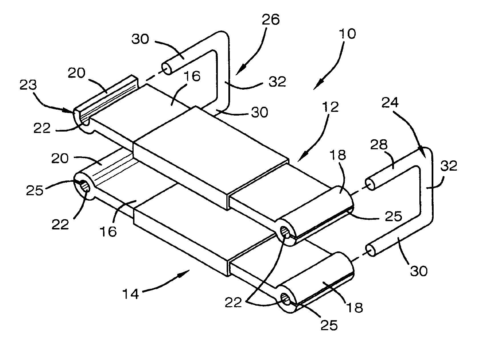
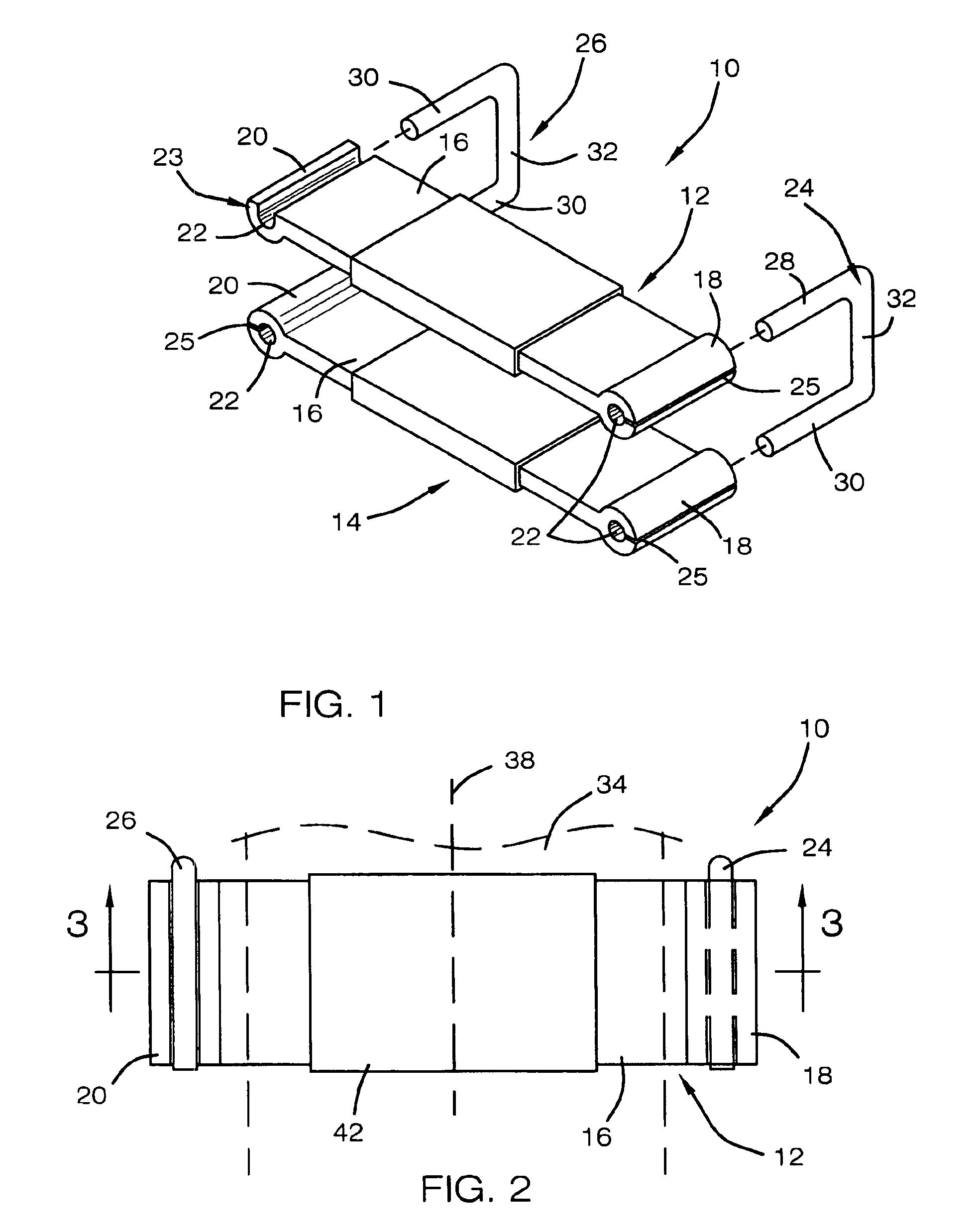
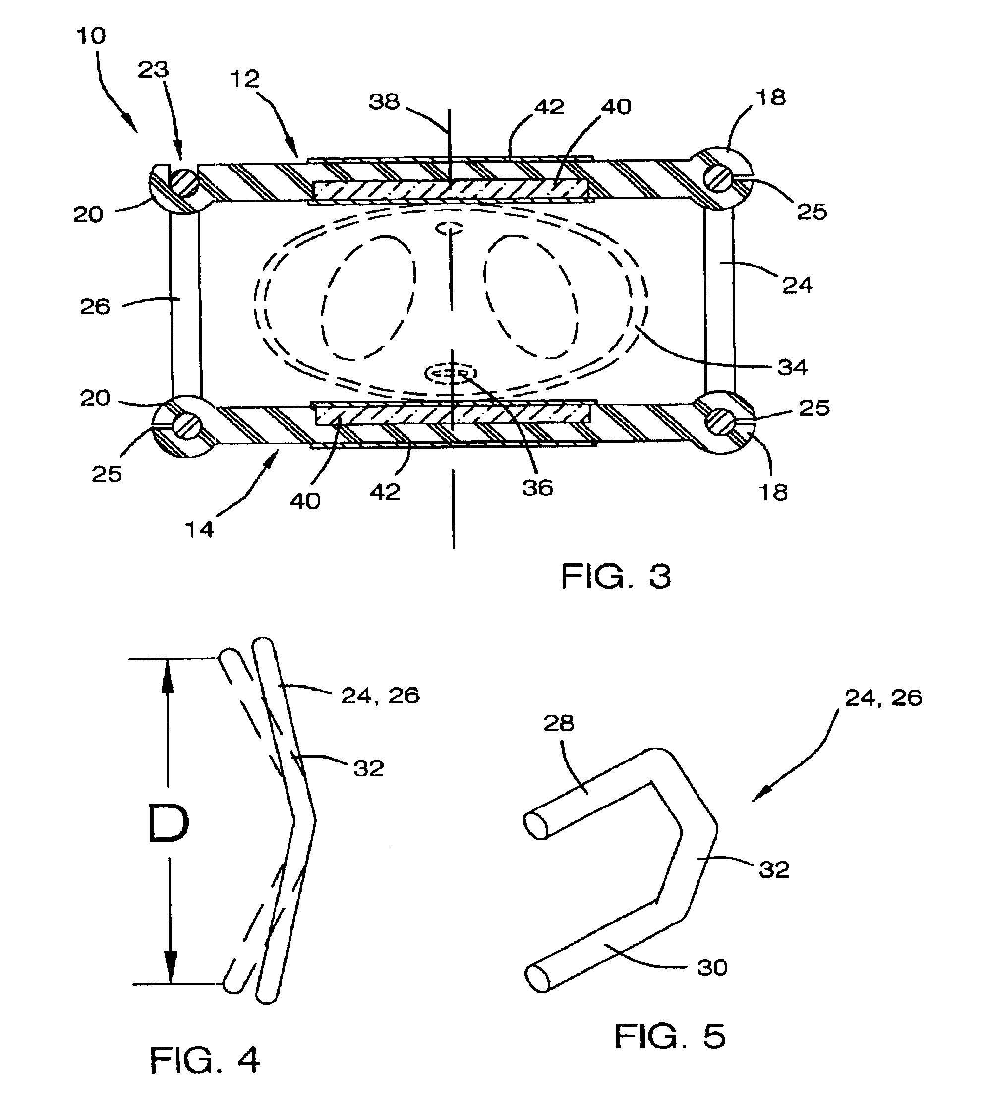
[0028]Referring now to the drawings, and particularly to FIGS. 1-5, a preferred embodiment of the external incontinence clamp of the present invention is shown and generally designated by the reference numeral 10.

[0029]In FIG. 1, a new and improved external incontinence clamp 10 of the present invention for preventing involuntary voiding of a bladder by restricting urine flow through the urethra of a penis is illustrated and will be described. More particularly, the external incontinence clamp 10 includes a first clamping member 12 and a second clamping member 14, which are rigid and generally rectangular shape and which are coupled together in a spaced relationship by generally U-shaped connection pins 24 and 26. Each member 12 and 14 have a mid portion 16 and two ends 18 and 20. The mid portion 16 is integral with and extends between the two ends 18 and 20. Preferably, the mid portion 16 of each member 12 and 14 is substantially rectangular in shape and is rigid.

[0030]Each end 18 ...


PUM


Abstract

An external incontinence clamp for stopping involuntary voiding of urine is provided. The clamp includes a first rigid member having opposed ends, each end defining a passage extending therethrough, a second rigid member having opposed ends, each end defining a passage extending therethrough, and two pins of generally u-shape. The pins are adapted to be received by the passages defined by the ends of the first rigid member and of the second rigid member so as to secure the first rigid member in a spaced and generally parallel relationship to the second rigid member. The penis is positioned between the first and second members so that the underside of the penis is in contact with the second member and the top surface of the penis is in contact with the first member, thereby stopping involuntary voiding of urine. A clamp kit includes a plurality of pins of different width to vary the force applied to the penis.

Description

BACKGROUND OF THE INVENTION[0001]1. Field of the Invention[0002]The present invention relates generally to male incontinency devices. More particularly, relating to an external incontinency device that is clamped to a male's penis to restrict urine flow through the urethra.[0003]2. Description of the Prior Art[0004]Due to the anatomy of a penis, external devices that are clamped or other wise secured to a penis can be very effective in controlling urine flow through the urethra. The urethra is a passageway through which urine travels and it is located on the under side of the penis relatively close to the skin surface. A very small amount of pressure applied to the urethra will collapse the passageway and prevent urine from flowing through. There are many know prior art devices that attempt to accomplish this to control or prevent involuntary voiding of a bladder or to prevent urine leakage.[0005]An example of an aforementioned device is disclosed in U.S. Pat. No. 4,942,866 to Timmo...

Claims


Application Information

Patent Timeline
Patent Type & Authority Patents(United States)
IPC IPC(8): A61B17/122A61B17/12A61F2/00
CPCA61B17/122A61F2/0054
Inventor RENNICH, HENRY
Owner RENNICH HENRY
Why Eureka
Try Eureka