Fire alarm system, fire sensor, fire receiver, and repeater

a fire alarm system and receiver technology, applied in the field of fire alarm systems, can solve the problems of difficult specification, fire alarm systems, and inability to utilize existing systems, and achieve the effect of reducing the time for specifying

Inactive Publication Date: 2005-11-01
HOCHIKI CORP
View PDF15 Cites 31 Cited by
  • Summary
  • Abstract
  • Description
  • Claims
  • Application Information

AI Technical Summary

Benefits of technology

[0018]The present invention has been made in view of the circumstances mentioned above. Accordingly, it is a first important object of the present invention is to quickly specify the inherent address of a fire sensor that issued a fire signal regardless of the number of lines, and reduce the time for specifying the place of a fire. A second importance object of the invention is

Problems solved by technology

Therefore, the fire alarm system has the disadvantage that it cannot utilize the existing systems.
Therefore, in a large building (e.g., a school) where a great number of transmitters 104 are disposed, it is fairly difficult to specify the transmitter 104 which is issuing an alarm, and consequently, there is a problem that guards or teachers cannot rush to the p

Method used


Image

  • Fire alarm system, fire sensor, fire receiver, and repeater
  • Fire alarm system, fire sensor, fire receiver, and repeater
  • Fire alarm system, fire sensor, fire receiver, and repeater

Examples


first embodiment

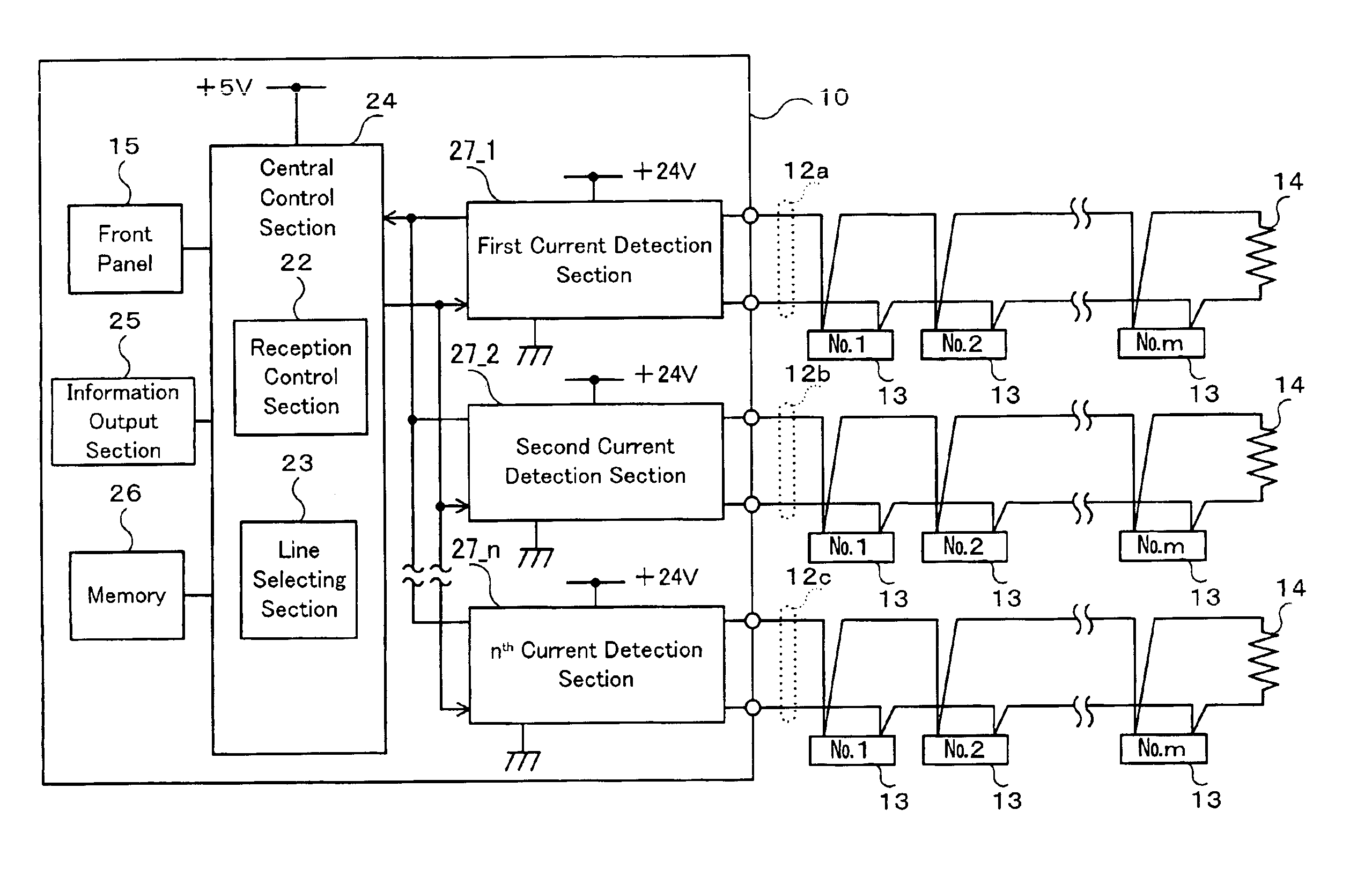
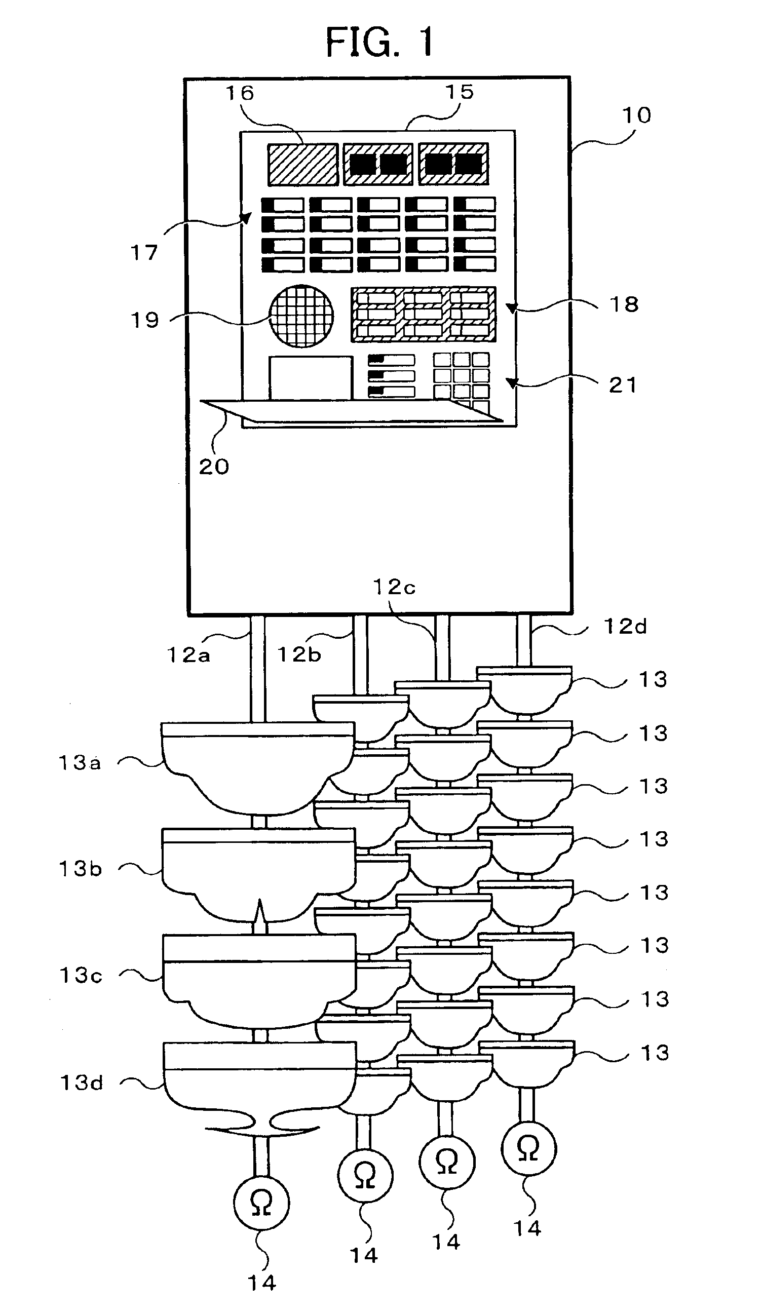
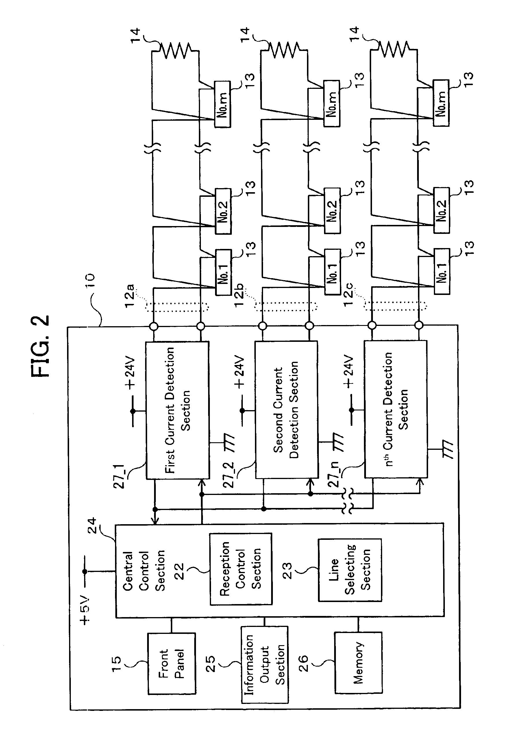
[0100]FIG. 1 shows a P-type fire alarm system (hereinafter referred to simply as a fire alarm system) constructed in accordance with the present invention. In the figure, a fire receiver 10 has n sensor lines 12a to 12d (in this embodiment, n=4). Each of the sensor lines 12a to 12d has a 2-line construction (pair construction of an L line and a C line), as described later. Each of the sensor lines 12a to 12d is connected in parallel with an arbitrary number of fire sensors 13. The sensor lines 12a to 12d are terminated at resistors 14, respectively.

[0101]If it detects a fire, the fire sensor 13 short-circuits the connected sensor line (short circuit between L and C lines). For example, as represented by the sensor circuit 12a, the fire sensors 13 may comprise various types of fire sensors such as a photoelectric smoke sensor 13a, a thermistor type heat sensor 13b, a differential sensor 13e, a constant-temperature sensor 13d, etc.

[0102]The fire receiver 10 has a front panel 15, which...

second embodiment

[0139]FIG. 10 shows a separable fire sensor 51 constructed in accordance with the present invention. In FIG. 10A, the fire sensor 51 consists of a main body portion 53 and a base portion 55. The main body portion 53 has a detection portion 15-1 for detecting by a scattered light method that smoke entered through smoke sensing windows 41, and a circuit board 15-2 for converting a scattered light quantity into a smoke concentration signal. The base portion 55 is equipped with an address transmission circuit 54 which has an address generating function, and a fire-information display light 60. If the main body portion 53 is mounted on the base portion 55, the circuit board 15-2 is electrically connected with the address transmission circuit 54. This state is shown in FIG. 10B.

[0140]The address transmission circuit 54 is equipped with a fire-information detection and power supply section 56, an address setting section 57, a modulation signal generating section 58, and a current modulatio...

third embodiment

[0154]FIG. 12 shows a disaster prevention system constructed in accordance with the present invention. In the figure, a receiver 120 is constructed so that various display buttons and control buttons are disposed in the front panel 121. For example, the receiver 120 is provided with an abnormal-situation display light 122 which is lit at the time of an abnormal situation such as a fire, a place display section 123 for displaying the place of an abnormal situation, a control section 124, and a sound output section 125. Inside a small lid 126, there is provided a control display section 127 for maintenance and inspection.

[0155]The receiver 120 has an A line, a C line, and Li lines. The number of Li lines corresponds to the number of warning areas. The Li line in FIG. 12 represents an L line for the ith warning area. A pair of A and C lines is referred to as an A-C line 128, which is connected to an arbitrary number of transmitters 150 (hereinafter referred to as n transmitters 150). A...


PUM


Abstract

Disclosed herein is a fire alarm system for connecting a plurality of fire sensors to sensor lines, and giving an alarm in response to fire information output from the fire sensor in a line unit. The fire alarm system includes a current modulation section and an address specification section. The current modulation section is used for maintaining a current flowing in the sensor line at a predetermined value for a predetermined time at the time of a fire, and modulating the current in accordance with the inherent address information of the fire sensor. The address specification section is used for sensing fire information by judging whether or not the current has been maintained at the predetermined value for the predetermined time, and also for specifying the inherent address of the fire sensor that issued the fire information, from the modulated state of the current.

Description

BACKGROUND OF THE INVENTION[0001]1. Field of the Invention[0002]The present invention relates generally to a fire alarm system, a fire sensor, a fire receiver, and a repeater, and more particularly to a fire alarm system which includes fire sensors provided at the predetermined places within a building, and a fire receiver for receiving a fire alarm signal from the fire sensors.[0003]2. Description of the Related Art[0004]FIG. 46 shows a proprietary type fire alarm system (hereinafter referred to as a P-type fire alarm system). This fire alarm system includes a fire receiver 2, which has a plurality of sensor lines L1 to Ln. Each of the sensor lines L1 to Ln are connected with a great number of fire sensors 1. The operations of the fire sensors 1 are collectively monitored for each sensor line by the fire receiver 2.[0005]The range to be monitored by the P-type fire alarm system is not the unit of a single fire sensor 1 but the unit of a sensor line (L1 to Ln) to which a plurality o...

Claims


Application Information

Patent Timeline
IPC IPC(8): G08B25/14G08B29/00G08B25/01G08B25/04G08B29/14G08B17/00
CPCG08B17/00G08B25/018G08B25/04G08B25/14G08B29/145
Inventor DOHI, MANABUNEMOTO, MASAHIKOYAMANO, NAOTOSHIMA, HIROSHIMATSUOKA, NAOYA
Owner HOCHIKI CORP
Why Eureka
Try Eureka