
Implantable bi-ventricular stimulation device and system, and bi-ventricular stimulation and sensing method

a bi-ventricular stimulation and sensing technology, applied in heart stimulators, electrophysiology, therapy, etc., can solve the problem of difficult detection of a pacing pulse evoked response to the first pacing circuit delivery of a pacing pulse, and achieve the effect of reducing the time gap (v-v) and reducing the time gap

Inactive Publication Date: 2005-11-01
ST JUDE MEDICAL
View PDF9 Cites 49 Cited by
  • Summary
  • Abstract
  • Description
  • Claims
  • Application Information

AI Technical Summary

Benefits of technology

[0015]An object of the invention is to provide an implantable heart stimulating device which overcomes the problem described in the previous paragraph. A further object is to provide such a device which is relatively uncomplicated and which can be implemented by relatively simple means.
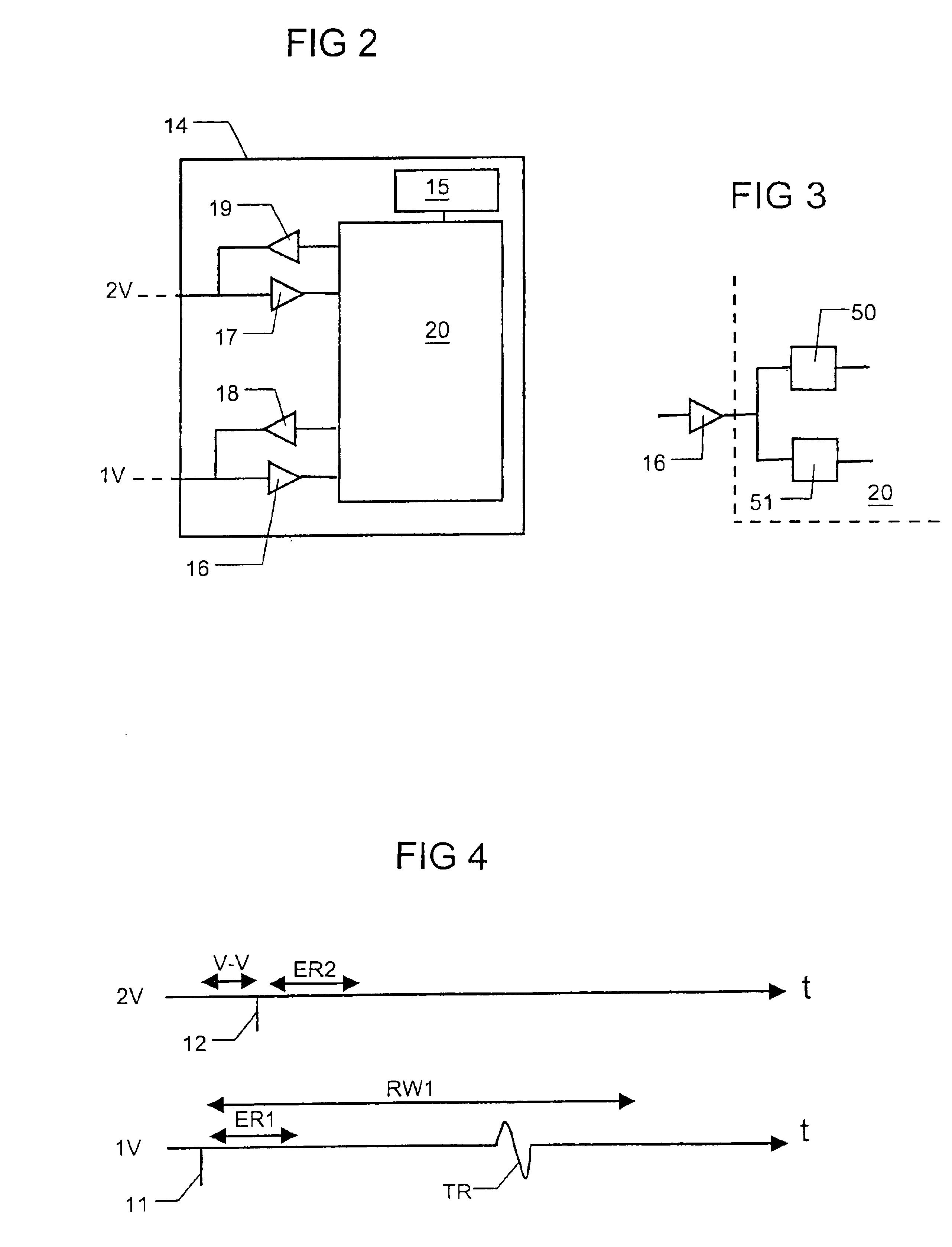
[0019]In another embodiment, the time gap (V-V) is decreased such that the pacing pulse delivered by the second pacing circuit comes substantially at the same time as the pacing pulse delivered by the first pacing circuit. “Substantially at the same time” as used herein means that the pacing pulse delivered by the second pacing circuit at least comes before the first time interval. This embodiment has the advantage that the second ventricle may still be paced although capture in the first ventricle can be confirmed.
[0021]Preferably, the temporary modification of the operation is performed during a number of time cycles. These time cycles can either follow immediately after each other or with a gap of one or more time cycles between them. In order to increase the reliability of the capture-detection concerning the first ventricle, the temporary modification preferably is carried out a number of times.

Problems solved by technology

In such a device, the detection of an evoked response to a pacing pulse delivered by the first pacing circuit is difficult, since a pacing pulse is delivered by the second pacing circuit during the time interval in which an evoked response is to be sensed by the first sensing means.

Method used


Image

  • Implantable bi-ventricular stimulation device and system, and bi-ventricular stimulation and sensing method
  • Implantable bi-ventricular stimulation device and system, and bi-ventricular stimulation and sensing method
  • Implantable bi-ventricular stimulation device and system, and bi-ventricular stimulation and sensing method

Examples


Embodiment Construction

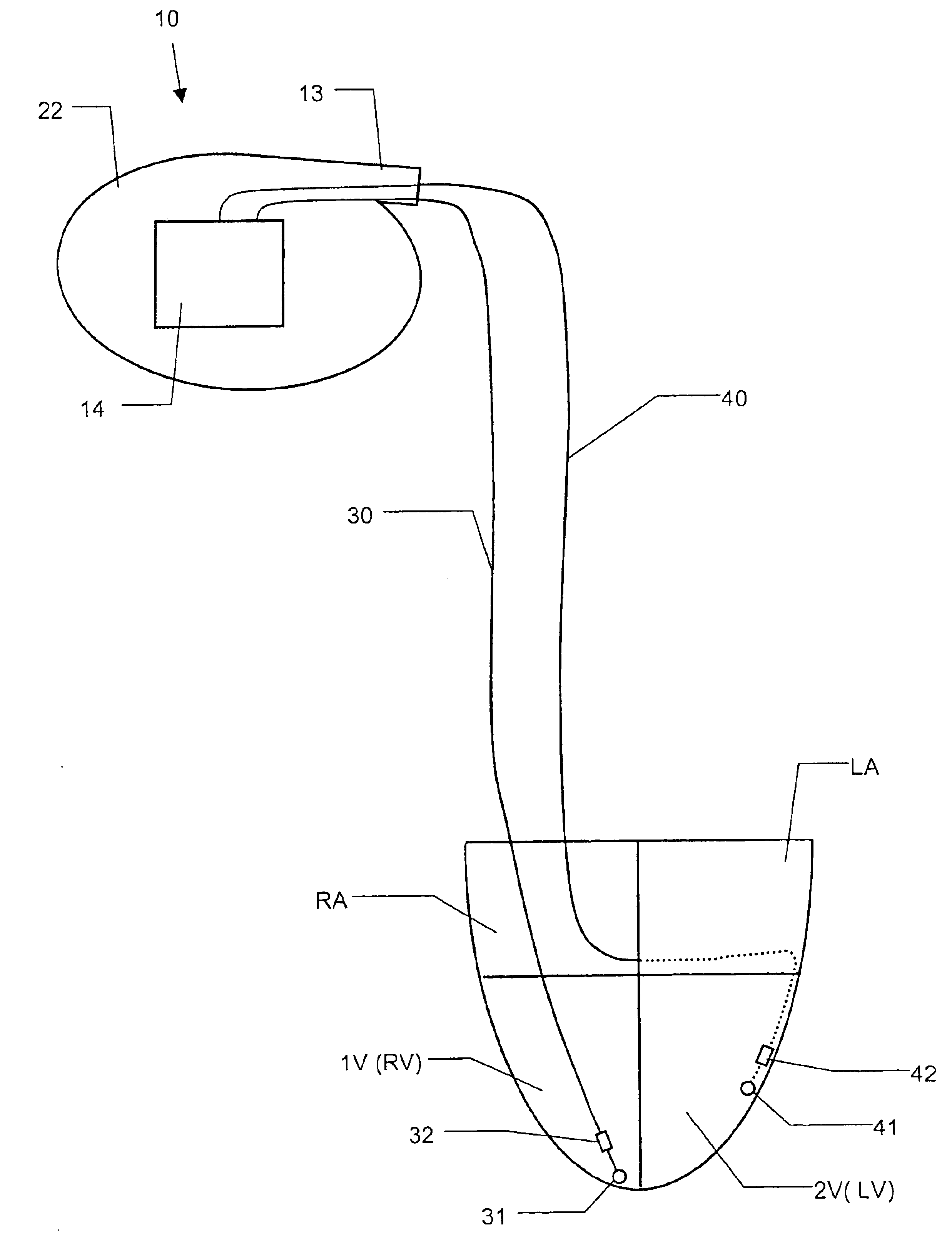
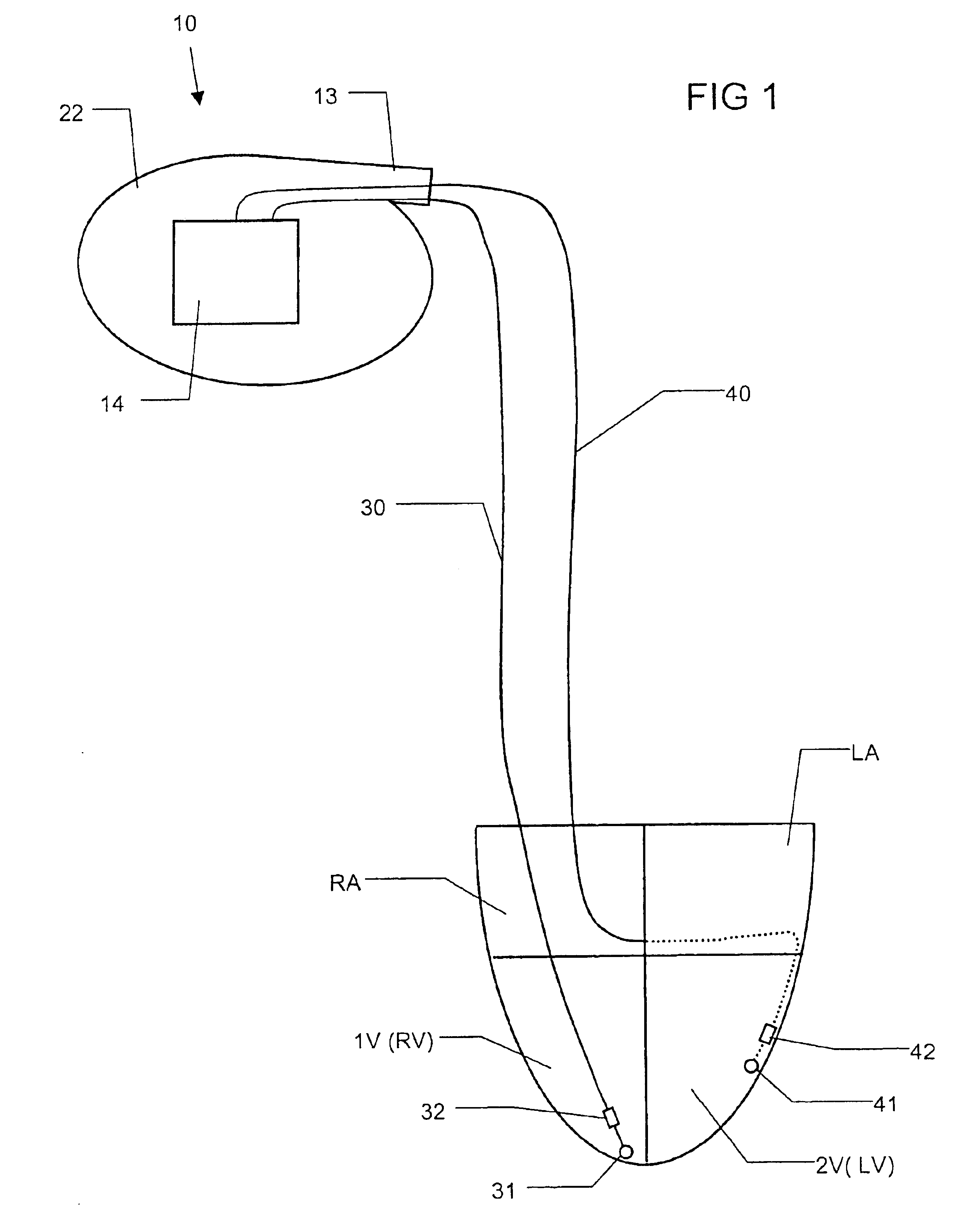
[0033]FIG. 1 schematically shows an implantable heart stimulating device 10 according to the invention. The device 10 has a housing 22. The housing 22 contains a control circuit 14. The device 10 also has a connector portion 13. Via the connector portion 13, the device 10 can be connected to different leads. In FIG. 1 the device 10 is connected to a first lead 30 and to a second lead 40. The device 10 together with the first 30 and the second 40 leads constitute an implantable heart stimulating system according to the invention. The first lead 30 includes a pacing and sensing electrode 31, 32. In this example this electrode 31, 32 is a bipolar electrode with a tip portion 31 and a ring portion 32, however, it is within of the scope of the invention to instead use unipolar electrodes, as is known to those skilled in the art. The second lead 40 has a corresponding electrode 41, 42.

[0034]FIG. 1 also schematically illustrates a heart with a right atrium RA, a left atrium LA, a first ven...


PUM


Abstract

An implantable bi-ventricular heart stimulating device has a control circuit that within a time cycle, delivers pacing pulses with both first and second pacing circuits with a time gap between a pacing pulse delivered by these pacing circuits. The time gap can be such that a pacing pulse delivered by the second pacing circuits falls substantially within a first time interval in which an evoked response can be expected to a pacing pulse delivered by the first pacing circuit. The control circuit performs a temporary modification of the operation of the device such that during at least one time cycle no pacing pulse is delivered by the second pacing circuit during the first time interval.

Description

BACKGROUND OF THE INVENTION[0001]1. Field of the Invention[0002]The present invention relates to an implantable heart stimulating device with which it is possible to stimulate both the ventricles of a heart, i.e. a bi-ventricular pacer.[0003]The invention also relates to a system including such a device and to a method for his bi-ventricular stimulation and sensing.[0004]2. Description of the Prior Art[0005]Many different implantable devices for stimulating a heart are known. The devices are normally able to sense the electrical activity of the heart. Some implantable devices are able to deliver stimulation pulses to both the left and right ventricles of the heart, and sometimes also to the left and right atria.[0006]Devices that are able to deliver stimulation pulses to both the left and right ventricles are also called bi-ventricular pacers. Such devices can be used to treat patients who suffer from different severe cardiac problems, e.g. patients suffering from congestive heart f...

Claims


Application Information

Patent Timeline
Patent Type & Authority Patents(United States)
IPC IPC(8): A61N1/368A61N1/362A61N1/37
CPCA61N1/368A61N1/3712A61N1/3684A61N1/36843
Inventor BJORLING, ANDERSHOLMSTROM, NILSHEDBERG, SVEN-ERIKUHRENIUS, ASA
Owner ST JUDE MEDICAL
Learn More