
Yard performance model based on task flow modeling

a task flow and performance model technology, applied in the field of railyard management, can solve the problems of inability to optimize, inability to meet the needs of service and resources, and inability to meet the needs of services and resources,

Inactive Publication Date: 2005-11-01
GE TRANSPORTATION SYST GLOBAL SIGNALING
View PDF24 Cites 53 Cited by
  • Summary
  • Abstract
  • Description
  • Claims
  • Application Information

AI Technical Summary

Benefits of technology

This model enables the Yard Master to determine if a railyard can accommodate scheduled trains by simulating task flows and labor allocation, allowing for the reordering of activities to ensure efficient train building and departure, thus optimizing the flow of trains and resource allocation within the yard.

Problems solved by technology

These services and the resources required are in limited supply.
Such an optimization is computationally infeasible.
However, the regional view of yards and corridors is feasible using modeling techniques, which provide accurate, but not necessarily perfect, views of the capacities of yards and corridors and the relevant services involved in moving trains through the system.
The train building process in a switchyard requires the use of tightly coupled and limited resources, with difficult constraints to be met as to train arrival and departure schedules.

Method used


Image

  • Yard performance model based on task flow modeling
  • Yard performance model based on task flow modeling
  • Yard performance model based on task flow modeling

Examples


Embodiment Construction

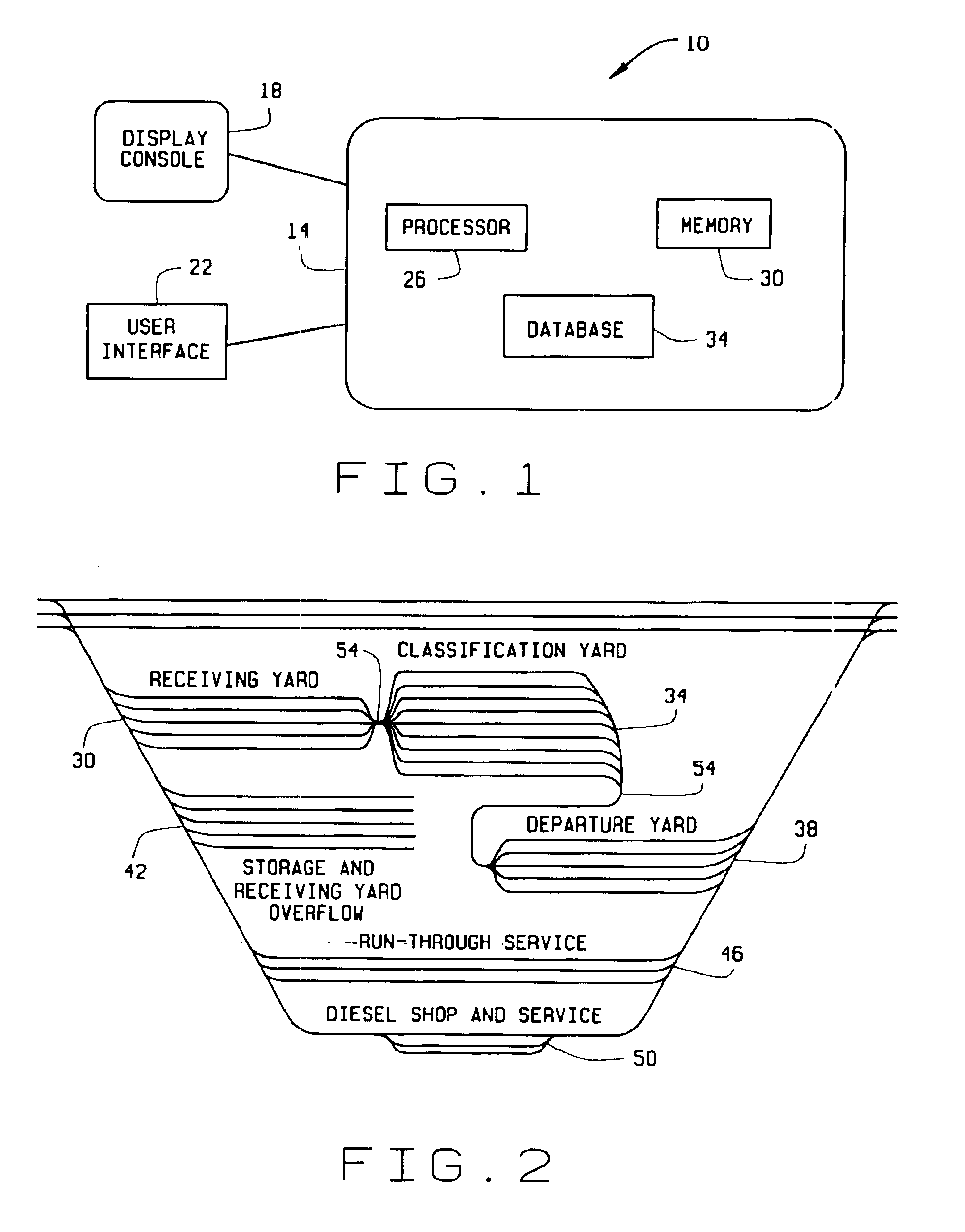
[0022]FIG. 1 is a diagram of a system 10 for implementing a yard performance model in accordance with one embodiment of the present invention. System 10 includes a computer 14, a display console 18 for viewing information input to and output from computer 14, and a user interface 22 for inputting information, parameters and data to computer 14. Computer 14 includes a processor 26 for executing all functions of computer 14, a memory storage device 30 for storing data and algorithms, and a database 34 for storing specific additional data. A yard master utilizes user interface 22 to input queries, parameters and data related to yard performance. In response to the yard master's inputs, computer 14 utilizes processor 26, memory 30, and database 34 to solve equations and execute algorithms implemented in the yard performance model.

[0023]FIG. 2 is a diagram of a railyard layout for illustrating particular railyard activities involved in implementation of the yard performance model in whic...


PUM


Abstract

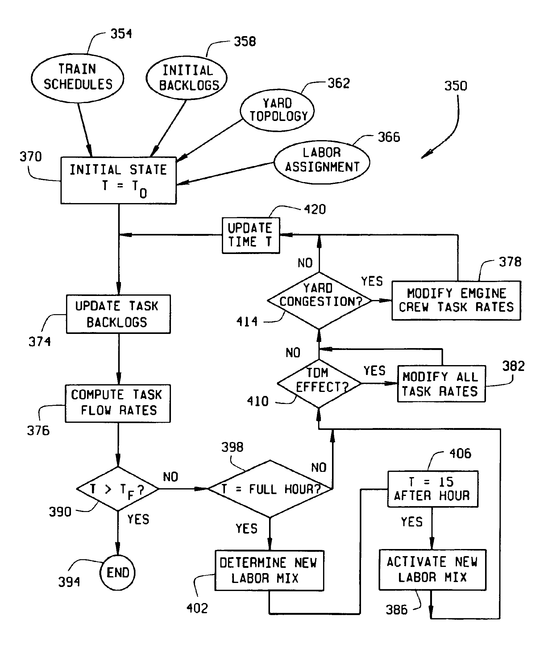
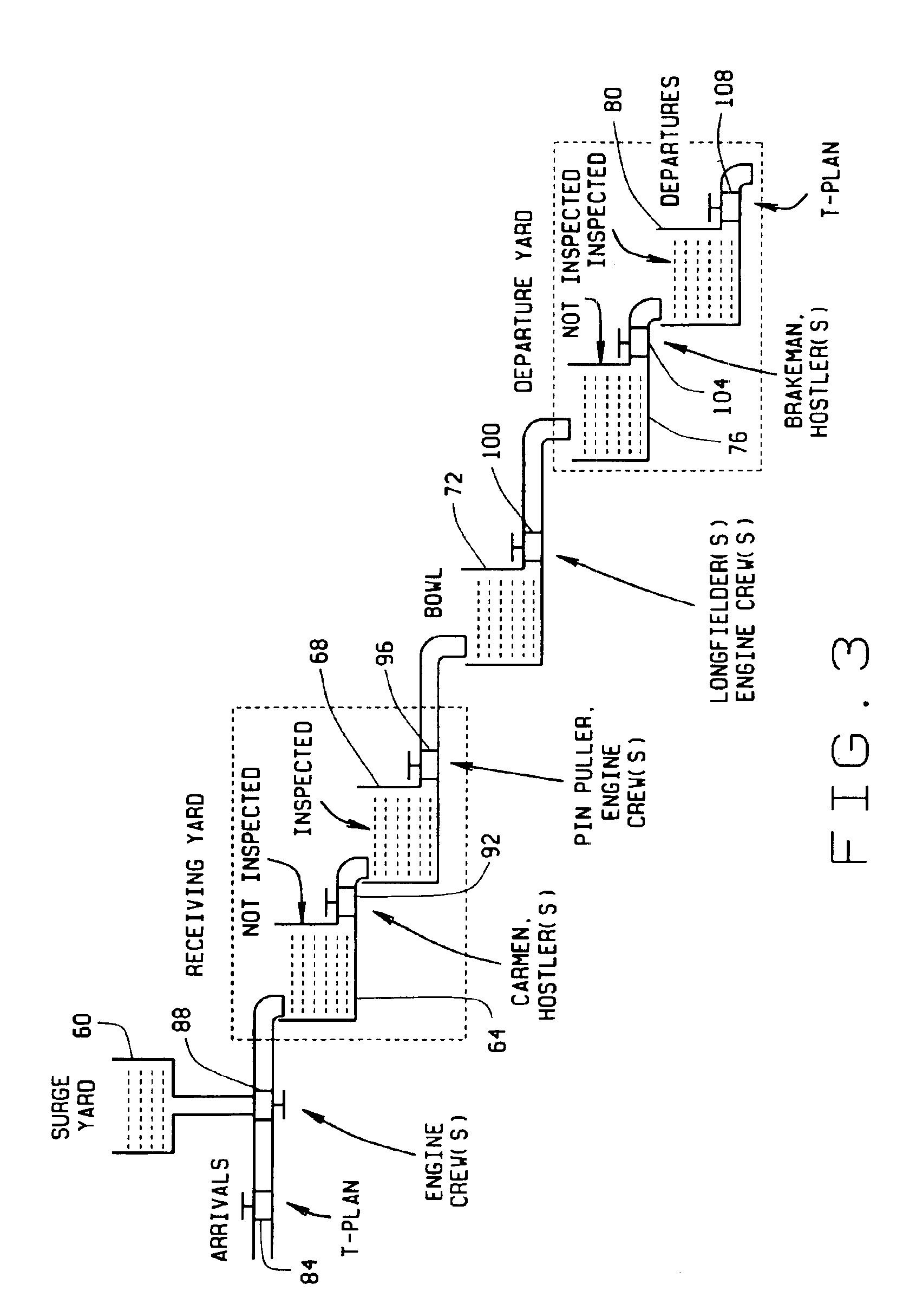
A method for managing railcar movement in a railyard based on the flow of railyard tasks, using a system that includes a computer including a processor, a memory device, and a database. The railyard includes six subyards including a surge yard, a receiving yard, a receiving inspected (RI) yard, a classification yard, a departure yard and a departure inspected (DI) yard. The method uses initial parameters, input to the computer, to simulate railyard task flow utilizing a yard performance model. Based on the simulation, the method determines if a train schedule can be met.

Description

CROSS REFERENCE TO RELATED APPLICATIONS[0001]This application claims the benefit of U.S. Provisional Application No. 60 / 173,436, filed Dec. 29, 1999, which is hereby incorporated by reference in its entirety.BACKGROUND OF THE INVENTION[0002]This invention relates generally to railyard management, and more particularly to a yard performance model for expediting and simplifying the process of moving railcars through a railyard from arrival to departure.[0003]A terminal area is primarily used to reorganize incoming freight into new trains, which then move the freight to further destinations. A terminal area comprises one or more switchyards and interconnecting rails, and the performance of the entire terminal area depends primarily on the activities within the terminal switchyard(s) and the efficient dispatch of traffic within the terminal area. Thus, a terminal area in effect can be visualized as a small railroad network in and of itself, with the primary activities of managing the di...

Claims


Application Information

Patent Timeline
Patent Type & Authority Patents(United States)
IPC IPC(8): G06F17/50G06F9/455B61L17/00B61L27/00G06Q10/06
CPCB61L17/00B61L27/0016B61L27/0055G06Q10/06G06Q10/06311B61L27/12B61L27/60
Inventor DONER, JOHN R.
Owner GE TRANSPORTATION SYST GLOBAL SIGNALING
Learn More