Full bearing 3D cushioning system

a full bearing, cushioning technology, applied in the direction of shoes, applications, footwear, etc., can solve the problems of insufficient cushioning, premature fatigue of joints and muscles, and discomfort of running on asphalt roads, so as to reduce the amount of force acting on the athlete and the effect of reducing friction

Inactive Publication Date: 2005-11-08
ADIDAS
View PDF74 Cites 30 Cited by
  • Summary
  • Abstract
  • Description
  • Claims
  • Application Information

AI Technical Summary

Benefits of technology

[0014]The invention relates to a sliding element for a shoe sole, in particular a sports shoe with an upper sliding surface and a lower sliding surface, wherein the lower sliding surface is arranged below the upper sliding surface so as to be slideable in at least two directions. A relative movement between the upper sliding surface and the lower sliding surface allows the foot to feel as if it is wearing a conventional shoe that contacts a surface with reduced friction, for example, a soft forest ground. The sliding movement of the surfaces distributes the deceleration of the sole over a greater time period. This, in turn, reduces the amount of force acting on the athlete and the momentum transfer on the muscles and the bones.
[0015]According to the invention, a sliding movement of the upper sliding surface relative to the lower sliding surface may occur in several directions. In contrast to the prior art, strains in the X-direction, as well as in the Y-direction, can therefore be effectively reduced. The two sliding surfaces interact without any side effects on the Z-direction. Thus, proven cushioning systems in the Z-direction can be combined, interference-free, with a sliding element in accordance with the invention.
[0016]Because the horizontal shear-movements can be optimized, the athlete can adjust the orientation of his or her lower extremities in such a way that the ground reaction force, which consists of the three components occurring in the X-, Y- and Z-directions and which is transferred as a load on the joints, is reduced. By reducing the lever arms in the knee joint and the ankle joint, the system can reduce the relevant frontal and transversal moments. Accompanying this reduction is a decrease of the shear-forces in the joints, which is also beneficial to the cartilage of the joints and the bases of the tendons. This is important to runners, because the typical injuries they suffer are degeneration of the cartilage and inflammation of the bases of the tendons.
[0017]In addition, a sliding element in accordance with the invention positively influences the moments and forces arising during running on cambered roads and during downhill running. A comparative study with conventional sole structures has shown that the sliding element allows measurable deflections, which noticeably reduce the loads arising during ground contact.

Problems solved by technology

The aforementioned horizontal forces in the X- and Y-directions are one reason why running on an asphalt road is considered uncomfortable.
The high transfer of momentum can cause premature fatigue of the joints and the muscles and may, in the worst case, even be the reason for injuries.
As a result, a torque, which cannot be sufficiently cushioned by compression of a sole material in the Z-direction alone, is exerted on the foot during first ground contact.
This problem becomes worse when the runner runs on a downhill path, since the angle between the shoe sole and the ground increases in such a situation.
With respect to this strain, the compression of the sole materials in the Z-direction alone again fails to provide sufficient cushioning.
Furthermore, during trail running on soft forest ground, roots or similar bumps in the ground force the foot during ground contact into an anatomically adverse inclined orientation.
This situation leads to peak loads on the joints.
One disadvantage of such constructions is that cushioning is only possible along a single path, as predetermined by the mechanical elements.
Another disadvantage of such constructions is that the horizontal cushioning is not decoupled from the cushioning in the Z-direction.
Accordingly, the complex multi-dimensional loads occurring during the first ground contact with the heel, in particular in the above discussed situations with inclined road surfaces, cannot be sufficiently controlled.
In particular, the system does not provide any cushioning during ground contact with the heel.

Method used


Image

  • Full bearing 3D cushioning system
  • Full bearing 3D cushioning system
  • Full bearing 3D cushioning system

Examples


Embodiment Construction

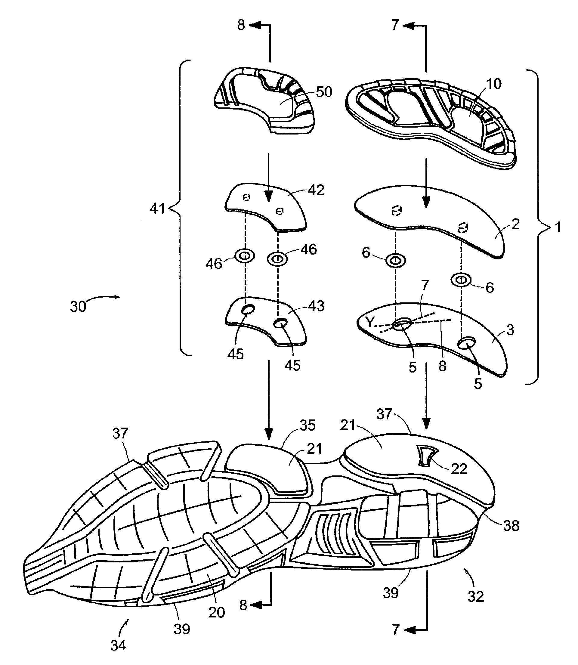
[0035]Embodiments of the present invention are described below. It is, however, expressly noted that the present invention is not limited to these embodiments, but rather the intention is that modifications that are apparent to the person skilled in the art are also included. In particular, the present invention is not intended to be limited to soles for sports shoes, but rather it is to be understood that the present invention can also be used to produce soles or portions thereof for any article of footwear. Further, only a left or right sole and / or shoe is depicted in any given figure; however, it is to be understood that the left and right soles / shoes are typically mirror images of each other and the description applies to both left and right soles / shoes. In certain activities that require different left and right shoe configurations or performance characteristics, the shoes need not be mirror images of each other.

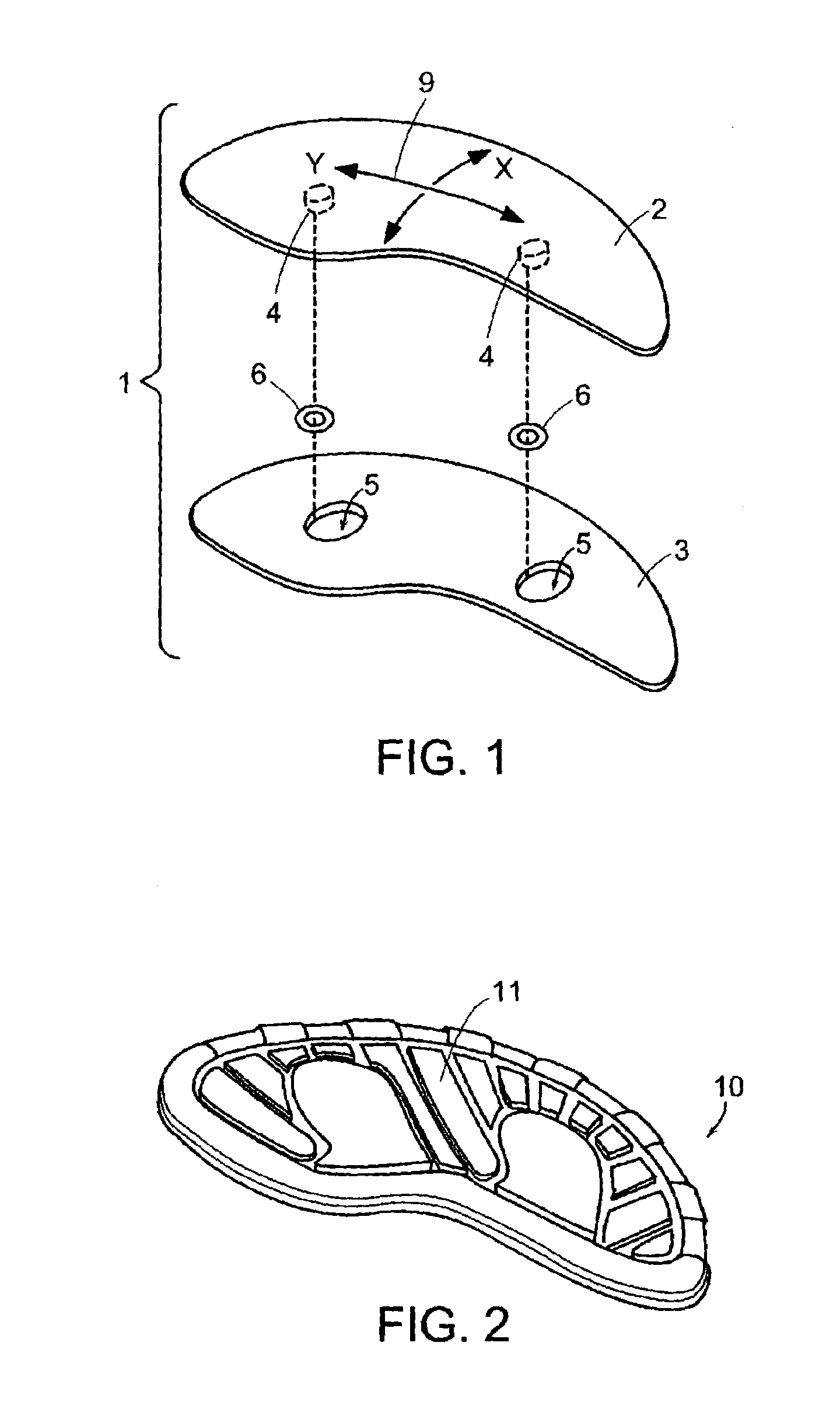
[0036]FIG. 1 depicts one embodiment of a sliding element 1 in acco...


PUM


Abstract

The invention relates to a sliding element for a shoe sole. The sliding element includes an upper sliding surface and a lower sliding surface, wherein the lower sliding surface is arranged below the upper sliding surface so as to be slideable in at least two directions. The upper sliding surface can form a lower side of an upper sliding plate and the lower sliding surface can form an upper side of a lower sliding plate. A relative sliding movement between the upper sliding surface and the lower sliding surface distributes the deceleration of the shoe sole over a greater time period and allows the foot to feel as if it is wearing a conventional shoe that contacts a surface with reduced friction, for example, a soft forest ground. As a result, the force acting on the wearer and the momentum transfer on his or her muscles and bones are reduced.

Description

CROSS-REFERENCE TO RELATED APPLICATION[0001]This application incorporates by reference, and claims priority to and the benefit of, German patent application serial number 10244435.8 that was filed on Sep. 24, 2002.TECHNICAL FIELD[0002]The present invention relates to a sliding element for a shoe sole, in particular a shoe sole with a sliding element that provides cushioning to the shoe in three dimensions.BACKGROUND[0003]Shoe soles should primarily meet two requirements. First, they should provide good friction with the ground. Second, they should sufficiently cushion the ground reaction forces arising during a step cycle to reduce the strains on the wearer's muscles and bones. These ground reaction forces can be classified into three mutually orthogonal components, i.e., a component occurring in each of the X-direction, the Y-direction, and the Z-direction. The Z-direction designates a dimension essentially perpendicular (or vertical) to the ground surface. The Y-direction designat...

Claims


Application Information

Patent Timeline
Patent Type & Authority Patents(United States)
IPC IPC(8): A43B13/12A43B13/02A43B13/18A43B13/14A43B5/00
CPCA43B13/12A43B13/122A43B13/125A43B13/14A43B13/18
Inventor MANZ, GERD RAINERHILL, JANSTESZYN, MICHAELKRABBE, BERTHOLD
Owner ADIDAS
Why Eureka
Try Eureka