
Mobile recycle bin stacker

a recycling bin and mobile technology, applied in the field of carrying devices, can solve the problems of back and arms at risk of injury, and achieve the effects of convenient unloading, convenient removal, and convenient support of the heaviest bins

Inactive Publication Date: 2005-11-08
GARCIA GARY M
View PDF17 Cites 30 Cited by
  • Summary
  • Abstract
  • Description
  • Claims
  • Application Information

AI Technical Summary

Benefits of technology

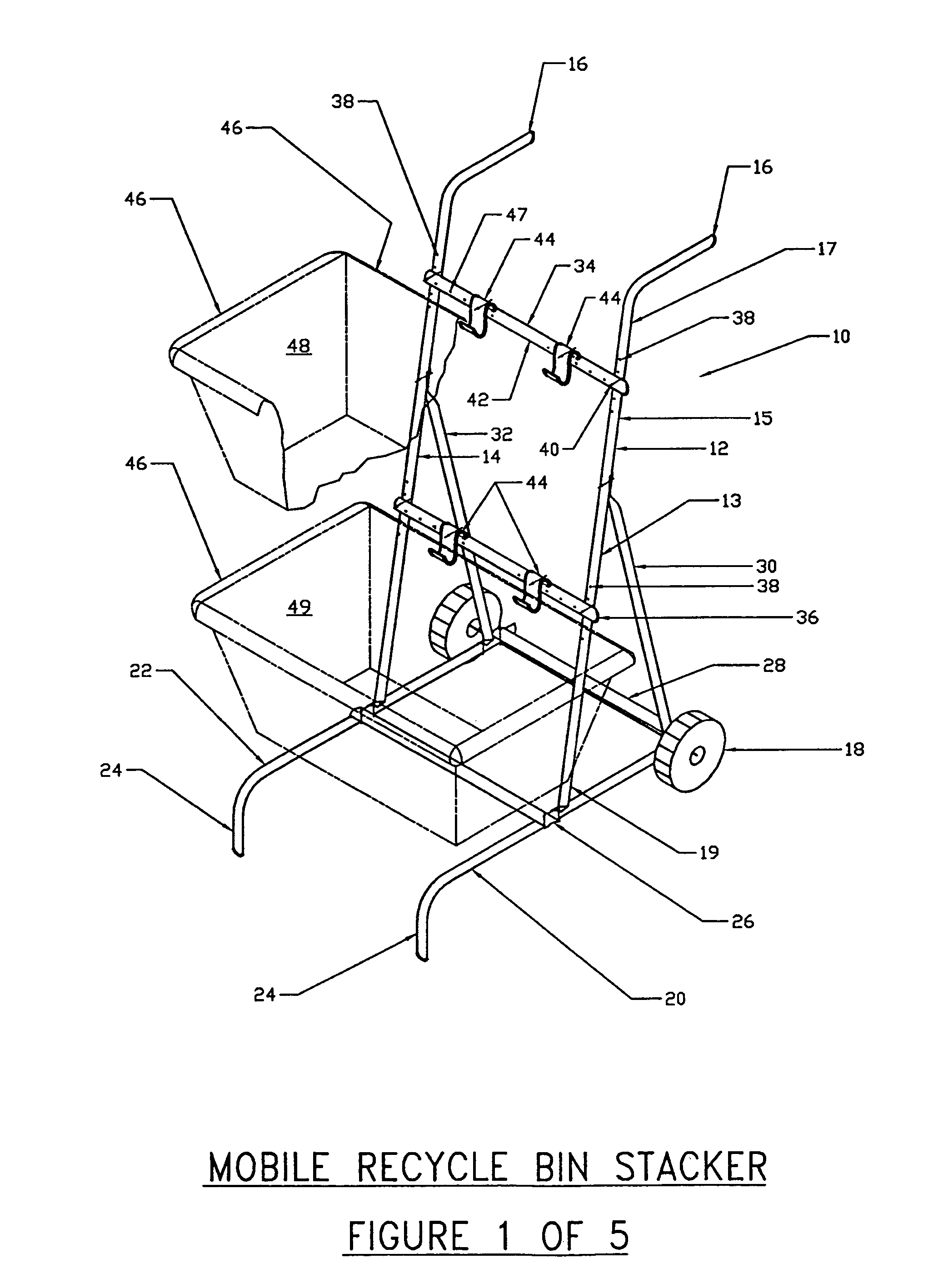
[0012]With this stacked arrangement, each bin can be easily unloaded and loaded onto the cart in an upward and downward vertical motion. This is advantageous because heavy loads are more optimally carried close to the user's body, as lifted more properly by the user's legs. Any other motion puts the back and arms at risk of injury due to the weight of the load. Hence, the present invention promotes a more safe lifting motion in that the user can position his hands on either side of the recycling bin, with the back held straight and the chest oriented towards the center of gravity of the load. The load is then lifted straight up off the hooks and carried to its destination. With the stacking arrangement, once the uppermost bin is removed, then the next bin down can be similarly lifted upwards. Also, the cart frame is constructed to facilitate supporting the heaviest bins on the uppermost hooks so that a user might not have to bend over to pick up and move the heaviest bins.
[0013]Accordingly, it is an object of the present invention to provide a wheeled recycling bin cart which facilitates removable placement of standardized recycling bins in a vertically stacked orientation.
[0016]It is an additional object of the present invention to provide a means for supporting recycling bins of varying size that is adjustable without tools.

Problems solved by technology

Any other motion puts the back and arms at risk of injury due to the weight of the load.

Method used


Image

  • Mobile recycle bin stacker
  • Mobile recycle bin stacker
  • Mobile recycle bin stacker

Examples


Embodiment Construction

[0027]Although the invention has been described in terms of a specific embodiment, it will be readily apparent to those skilled in this art that various modifications, rearrangements and substitutions can be made without departing from the spirit of the invention. The scope of the invention is defined by the claims appended hereto.

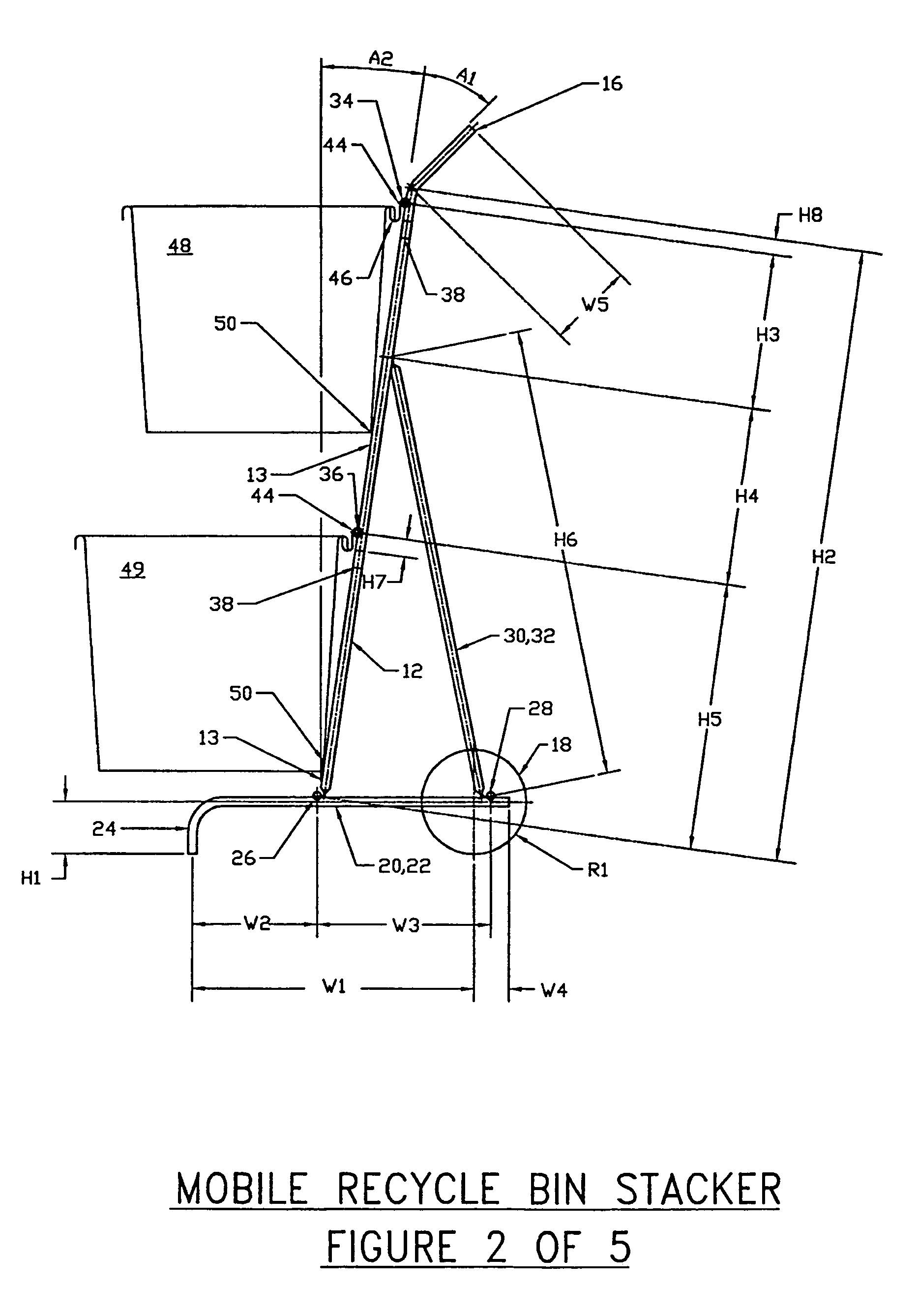
[0028]Referring now to FIG. 1, the recycling bin cart 10 is shown with various parts drawn in phantom to more fully illustrate the invention. A first side member 12 and second side member 14 are shown parallelly disposed, each having a front edge 13, a back edge 15, a top portion 17 and a bottom portion 19. Each top portion has a handle 16 curving backwards and angled upwards to facilitate a more horizontal disposition of the handle when the cart is tilted back on its wheels 18. Each side member 12, 14 is attached to corresponding leg member 20 and 22 which each support a wheel 18 at the back and have a curved leg support appendage 24 at the front. The car...


PUM


Abstract

A mobile bin cart which supports recycling bins. The cart has a vertically oriented frame with wheels at the bottom for tilting back and moving the cart. A plurality of horizontal cross braces spans the frame, with each brace vertically mounted above the others. At least two contoured support brackets are adjustably mounted to each cross brace so that the hook elements are oriented vertically upwards. The circumferential lip of a standard recycling bin is then supported by the hook elements, with the bin swinging backward to butt against the cart frame for additional support. The bins can then be removed and replaced with a vertical lifting motion hence making loading and unloading the cart much easier for the user.

Description

[0001]This is a continuation-in-part of application Ser. No. 09 / 028,182 filed on Feb. 23, 1998, now abandoned, which is a continuation-in-part of application Ser. No. 08 / 623,246 filed on Mar. 28, 1996, now abandoned.FIELD OF INVENTION[0002]This invention relates to a carrying device which facilitates releasable attachment of recycling bins in a stacked arrangement onto a wheeled cart for transport.BACKGROUND OF THE INVENTION[0003]Recycling of waste products is a continuing concern of individuals and communities as natural resources are depleted and landfills filled to capacity. In many places, the government mandates the separation of garbage into recyclable categories, such as glass, plastics, paper, etc. Standardized recycling bins facilitate the efficient collection of such recyclable materials. When filled with materials such as metal cans or glass, these bins can often become heavy and cumbersome to move.[0004]As a result, the prior art includes a variety of carts for moving re...

Claims


Application Information

Patent Timeline
Patent Type & Authority Patents(United States)
IPC IPC(8): B62B1/00B62B1/14B62B1/26
CPCB62B1/14B62B1/26B62B2202/12B62B2202/20B62B2203/40
Inventor GARCIA, GARY M.
Owner GARCIA GARY M
Learn More