
Vertical axis windmill

a vertical axis windmill and wind turbine technology, applied in the direction of rotors, greenhouse gas reduction, vessel construction, etc., can solve the problems of friction loss in the rotary mechanism, whirling braking, airstream sticking to the blades, etc., and achieve the effect of high advantageous results

Inactive Publication Date: 2005-11-08
TSIPOV MICHAEL
View PDF7 Cites 32 Cited by
  • Summary
  • Abstract
  • Description
  • Claims
  • Application Information

AI Technical Summary

Benefits of technology

[0005]When the windmill is designed in accordance with the present invention, it eliminates the disadvantages of the prior art and provides for the highly advantageous results.

Problems solved by technology

Such losses include losses for friction in a rotary mechanism, friction of blades in contact with air, losses connected with viscosity of air which causes sticking of airstreams on the blades, braking whirling, etc.
The main loss is however loss for a front resistance of blades.

Method used


Image

  • Vertical axis windmill
  • Vertical axis windmill
  • Vertical axis windmill

Examples


Embodiment Construction

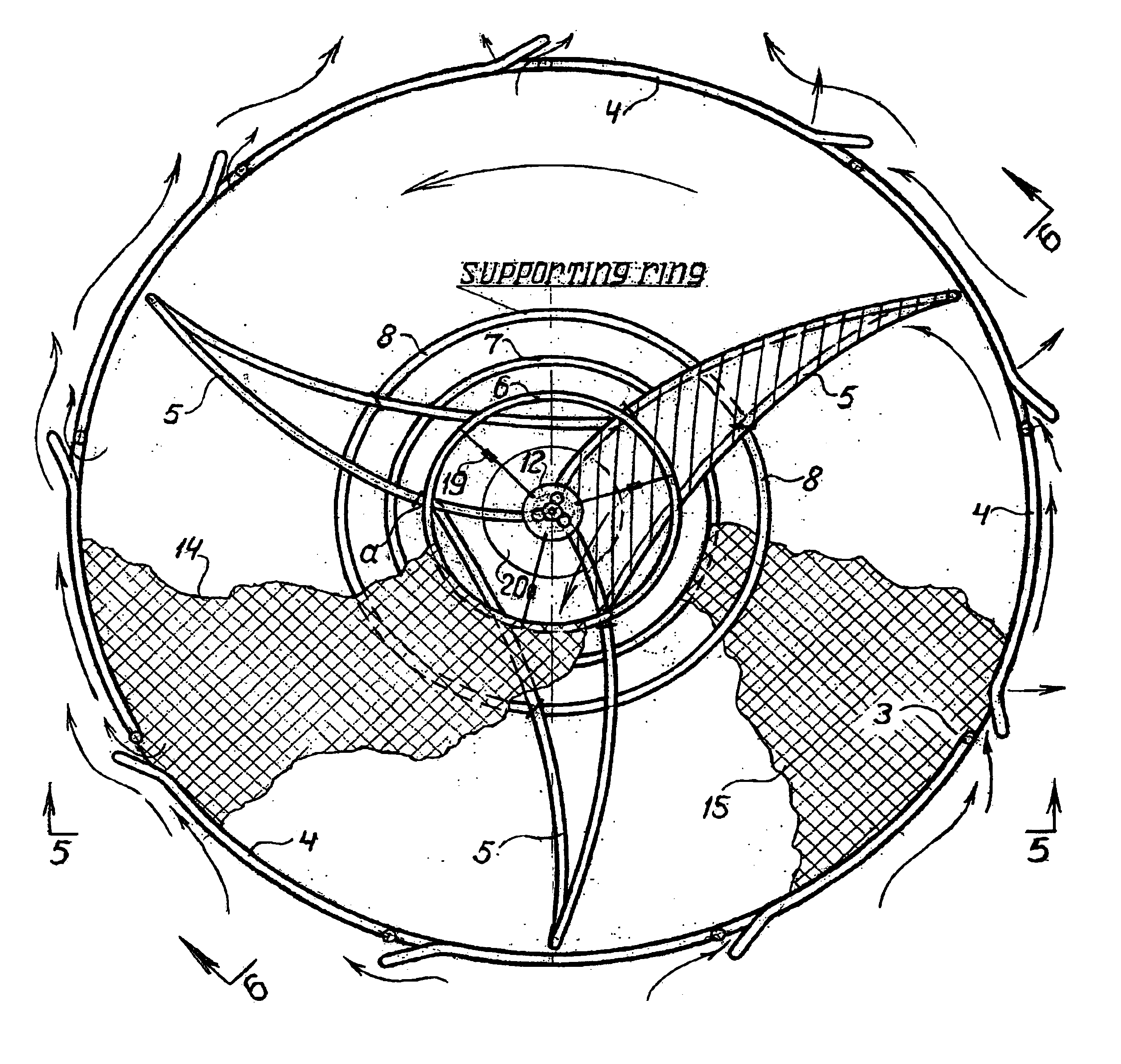
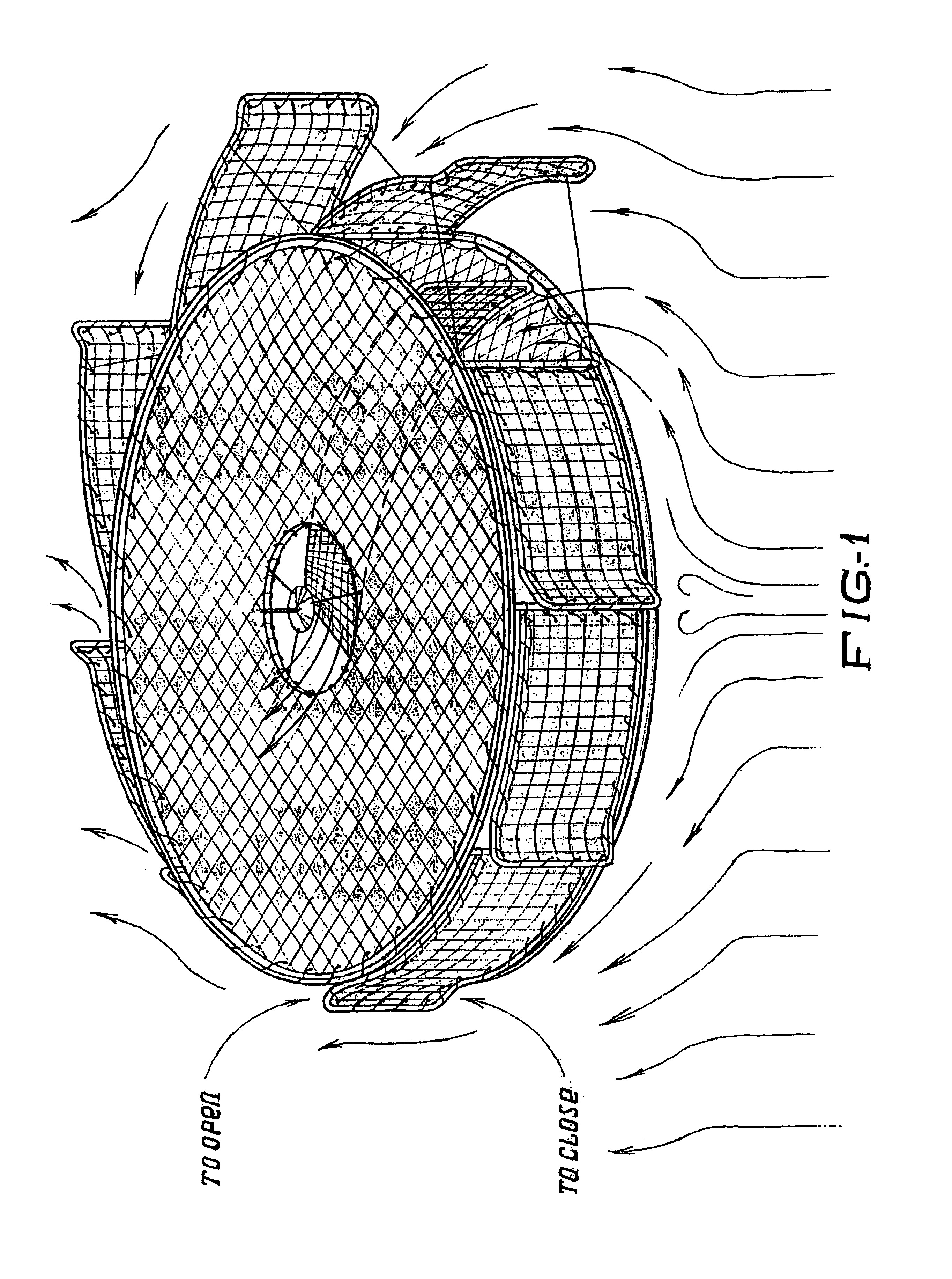
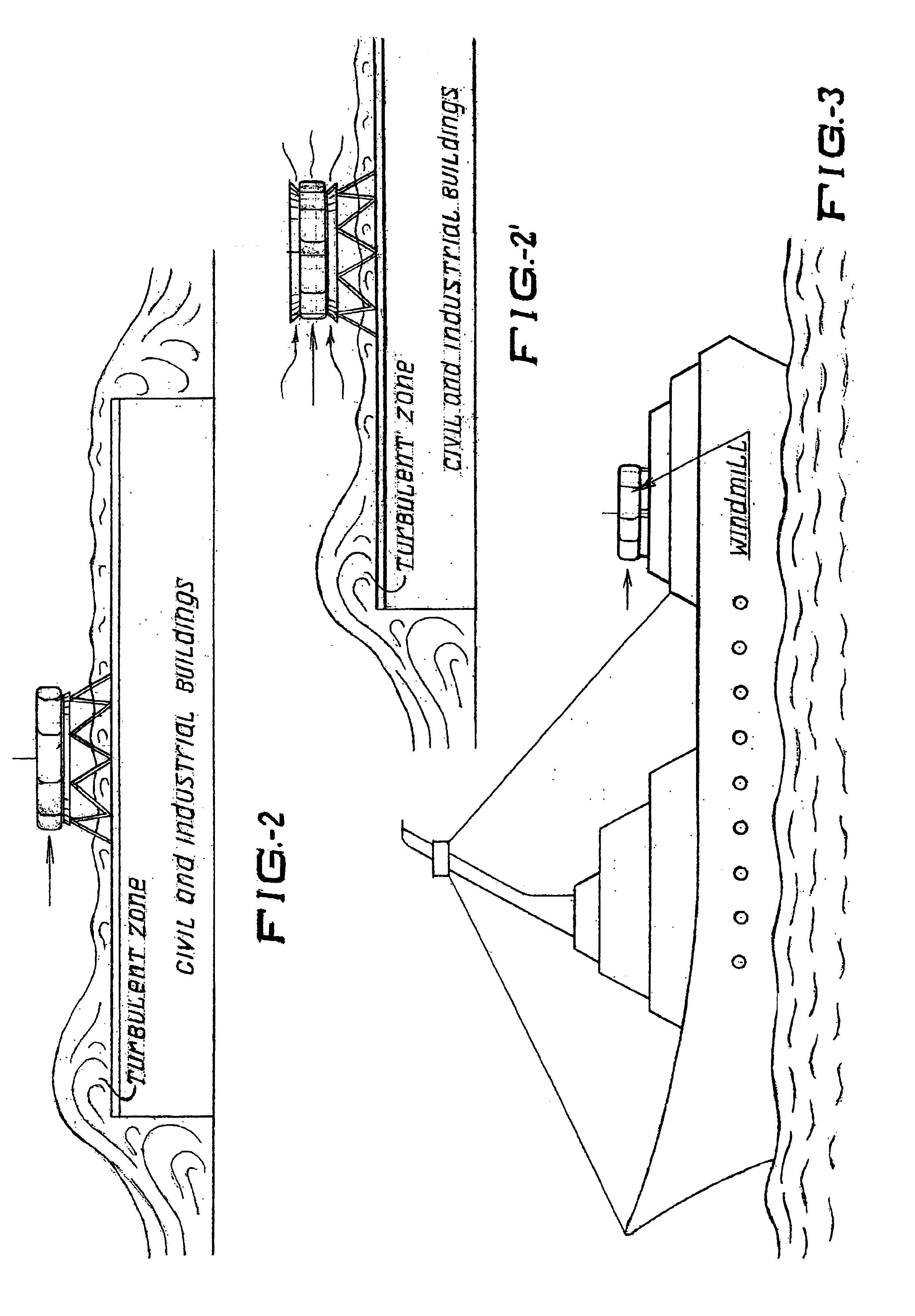
[0021]A windmill in accordance with the present invention has a substantially cylindrical shape with a very small axial extension. An immovable frame of the inventive windmill includes two circular elements 1 and 2 which are located horizontally and composed in the shown embodiment of pipes. Vertical supports 3 extend between the circular elements 1 and 2 and are also composed of pipes. The lower end of the supports can be welded to the lower circular element 1 as shown in FIG. 8. The upper end of the supports can have a bolt connection with the circular element 2. For this purpose a bolt 13 is screwed into a nut which is welded to an upper part of the support 3 as shown in FIG. 9. Each vertical support 3 carries a base element 4 which is composed also of pipes as shown in FIGS. 4, 7, 8, 10, 11. The spaces formed by the contours of the circular elements 1 and 2 and the contours of the gates elements 4 can be filled with an elastic material. For example a technical fabric 14, 15 can ...


PUM


Abstract

A vertical axis windmill has an immovable, hollow circumferential frame having a plurality of peripheral openings, and rotatable turbine arranged inside the frame and connectable to a generator of electric energy, the turbine having a plurality of vanes each having a working side and a non-working side, and a plurality of gate elements turnably connected with the frame for closing and opening of the openings of the frame by wind flowing substantially in a horizontal plane, the gate elements and the vanes of the turbine being formed so that at one side of the frame the wind opens the gate members by turning them in a predetermined direction, so that at one side the wind turns the gate elements so as to open corresponding ones of the openings, enters the frame through the corresponding opened openings and acts on the working side of corresponding ones of the vanes so as to rotate the turbine in the predetermined direction, while at the same time at the other side of the frame the wind closes other offset gate members.

Description

BACKGROUND OF THE INVENTION[0001]The present invention relates to devices for capturing the power of wind, and more particularly to such devices wherein a wind power is converted to rotational mechanical energy.[0002]More particularly, the present invention relates to windmill having an axis of rotation which is oriented generally perpendicular with respect to the surface of the earth, or so-called vertical axis windmills. Windmills of the above mentioned general type are known in the art. One of such windmills is disclosed in our U.S. Pat. No. 4,822,239. The existing windmills with a vertical axis of rotation operate in a horizontal plane and, in addition to the useful energy, give away a significant part of it for compensation of mechanical, hydraulic, and aerodynamic losses. Such losses include losses for friction in a rotary mechanism, friction of blades in contact with air, losses connected with viscosity of air which causes sticking of airstreams on the blades, braking whirlin...

Claims


Application Information

Patent Timeline
Patent Type & Authority Patents(United States)
IPC IPC(8): F03D3/06F03D3/00
CPCF03D3/067F05B2260/72Y02B10/30Y02E10/74Y10S415/907
Inventor TSIPOV, MICHAEL
Owner TSIPOV MICHAEL
Learn More