
Stacked polyurethane polishing pad and method of producing the same

a polyurethane and polishing pad technology, applied in the field of polyurethane pads and methods, can solve the problems of affecting the performance of the pad, not wanting to impose any deviation, and more material being removed from some spots than from other spots, and achieve the effect of uniform material removal rate and uniform material removal ra

Active Publication Date: 2007-03-13
ELECTRONICS SURFACING MATERIALS INC +1
View PDF10 Cites 3 Cited by
  • Summary
  • Abstract
  • Description
  • Claims
  • Application Information

AI Technical Summary

Benefits of technology

The designed polyurethane pad achieves uniform material removal rates and uncompromised planarization of semiconductor wafers, resisting water penetration and permanent deformation, thereby enhancing the overall polishing process efficiency and pad longevity.

Problems solved by technology

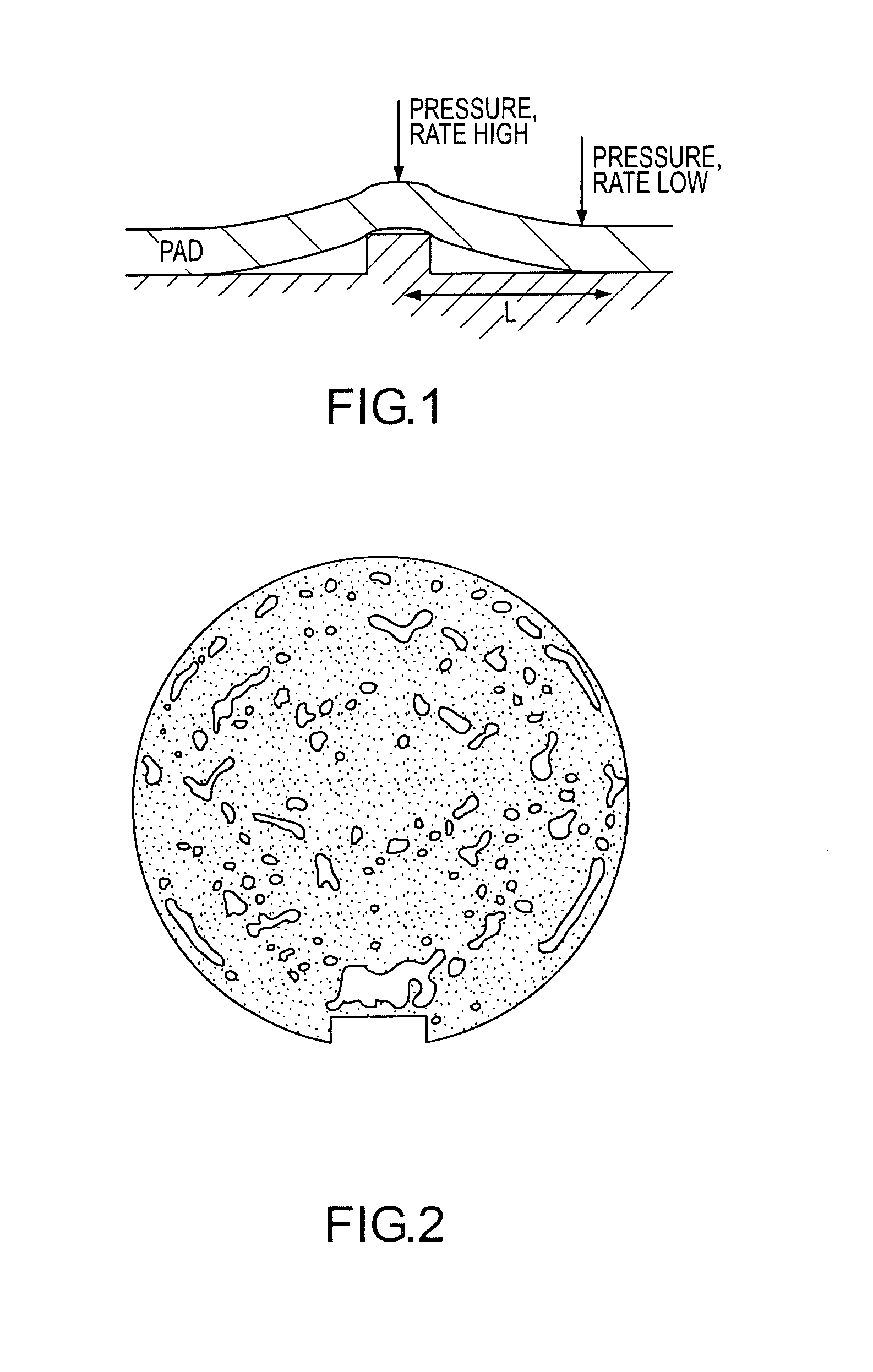
These undulations are completely unrelated to the surface features of the wafer and planarizing them generally leads to more material being removed from some spots than from other spots, an undesirable effect (FIG. 2).
Additionally, it is also not desired to impose any deviations from flatness exhibited by the platen onto the wafer.
If either the subpad or the top pad undergo significant permanent deformation, a degradation of the performance of the pad could result.
This could happen for a plurality of reasons of which we consider two: 1) A permanent deformation can change the elastic modulus of the material, putting it in an undesirable range; and 2) a nonuniform change in the elastic modulus can change the uniformity of the removal on a wafer, also highly undesirable.

Method used


Image

  • Stacked polyurethane polishing pad and method of producing the same
  • Stacked polyurethane polishing pad and method of producing the same
  • Stacked polyurethane polishing pad and method of producing the same

Examples


Embodiment Construction

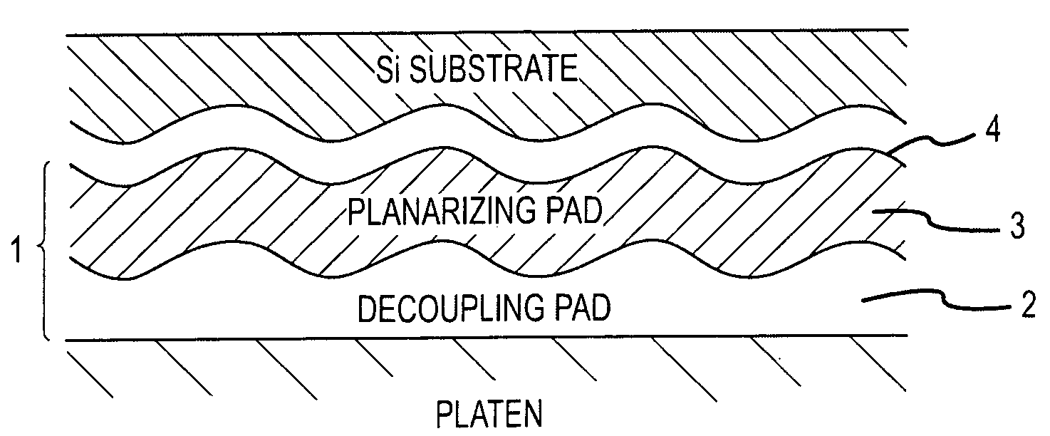
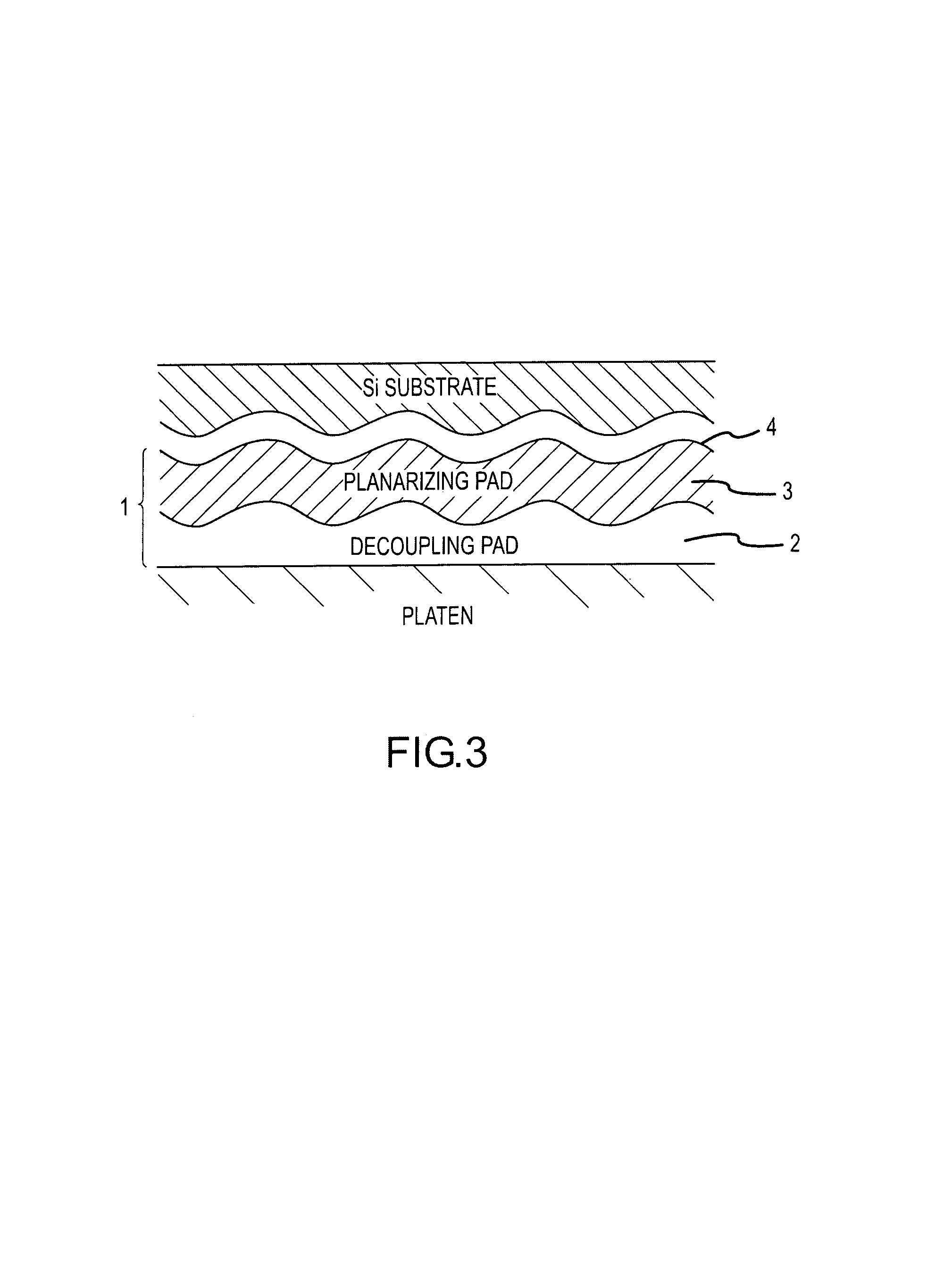
[0023]A polyurethane pad in accordance with the present invention is identified as a whole with reference numeral 1. It has a sublayer which is identified with reference numeral 2, and a top layer which is attached to the sublayer and identified with reference numeral 3. A polishing surface 4 of the polyurethane pad is provided on the top layer of the pad.

[0024]In accordance with the present invention, the sublayer 2 has a modulus of elasticity between 300 psi and 5000 psi and a preferred range of 1500 psi to 3500 psi. The compressibility of the sublayer of the polyurethane polishing pad in accordance with the present invention is less than 30% at 73 psi with a preferred range of 5% to 15% at 73 psi. The top layer 3 of the polyurethane polishing pad in accordance with the present invention has a modulus of elasticity which is greater than the modulus of elasticity of the sublayer, and at the same time has a compressibility which is smaller than the compressibility of the sublayer.

[0...


PUM

PropertyMeasurementUnit
distanceaaaaaaaaaa
modulus of elasticityaaaaaaaaaa
compressibilityaaaaaaaaaa

Abstract

A polishing pad has a sublayer; a top layer attached to the sublayer, the sublayer having a modulus of elasticity between 300 and 5000 psi and a compressibility of less than 30% at 73 psi, wherein the top pad has a modulus of elasticity which is greater than the modulus of elasticity of the sublayer and a compressibility which is smaller than a compressibility of the sublayer.

Description

BACKGROUND OF THE INVENTION[0001]The present invention relates to polyurethane pads and methods of producing the same.[0002]The present invention generally relates to polishing pads, in particular to chemical-mechanical polishing (CMP) pads. CMP is a process step in the semiconductor fabrication sequence that has generally become an integral part of the manufacture of semiconductor wafers. The process is used in a variety of applications in the semiconductor fabrication sequence. Different applications are sometimes best optimized with different polishing pad types and configurations, however, this invention is not application specific.[0003]In any of these CMP processes, the silicon substrate is forcibly placed in direct contact with a moving polishing pad. A wafer carrier applies pressure against the backside of the substrate, usually while simultaneously forcibly applying rotation. During this process a slurry is made available, and is generally carried between the wafer and the ...

Claims


Application Information

Patent Timeline
Patent Type & Authority Patents(United States)
IPC IPC(8): B24D11/00
CPCC08L75/04B24B37/22
Inventor RENTELN, PETER
Owner ELECTRONICS SURFACING MATERIALS INC
Learn More