Reciprocating syringes

Inactive Publication Date: 2005-11-08
STC UNM
View PDF18 Cites 16 Cited by
  • Summary
  • Abstract
  • Description
  • Claims
  • Application Information

AI Technical Summary

Benefits of technology

[0014]It is, therefore, an object of the present invention to provide a syringe that permits both injection and aspira

Problems solved by technology

Single-handed aspiration with a standard syringe is possible, but is difficult and awkward.
There are several problems with this method including: 1) fine control of the syringe is effectively lost (which is important when there is a sharp needle in delicate living tissues); 2) the entire syringe tends to rotate, further degrading control; 3) due to the size of the syringe components relative to the dimensions and strength of the human hand this method is extremely difficult with syringes larger than 10 cc (i.e. 20 cc or 60 cc); and 4) the force of aspiration is generated by weak intrinsic flexors of the hand, without using powerful flexors of the thumb and forearm, resulting in a weaker aspiration.
Thus, this single-handed method is unsatisfactory.
Unfortunately, variations of this method are best demonstrated by drug addicts who inject themselves with drugs.
The alternative thumb method has several disadvantages: 1) although a degree of control is maintained, it is not the fine control of the fingers, but the more coarse control of the forearm musculature; 2) power of the aspiration is weak, because it is accomplished by the extensors of the thumb; 3) full aspiration is difficult to achieve without changing the handgrip; 4) the syringe is generally pointing toward an operator which is the opposite direction required in a medical procedur

Method used


Image

  • Reciprocating syringes
  • Reciprocating syringes
  • Reciprocating syringes

Examples


Embodiment Construction

Definitions

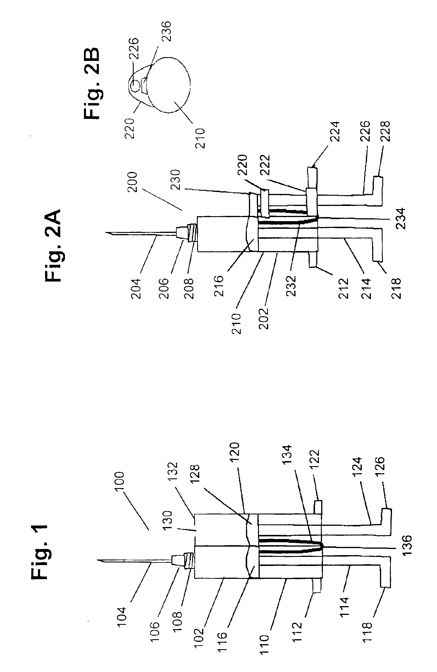
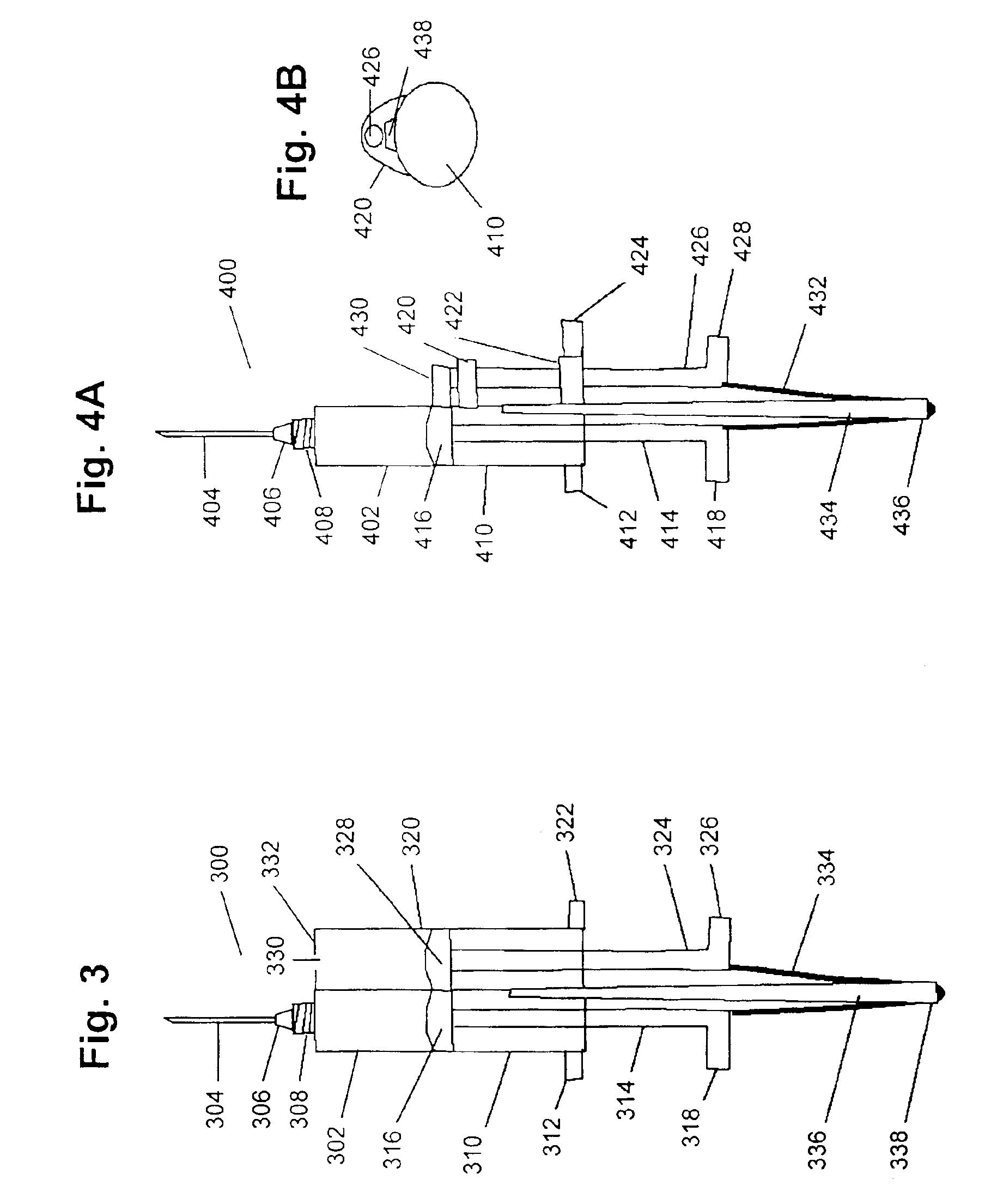
[0039]For the purposes of the present invention, the term “axial direction of a syringe” refers to the line along a center axis of a syringe from its distal end to its proximal end or from its proximal end to its distal end.

[0040]For the purposes of the present invention, the term “proximal” refers to a direction towards a user of a syringe. For the purposes of the present invention, the term “distal” refers to a direction away from the user of the syringe.

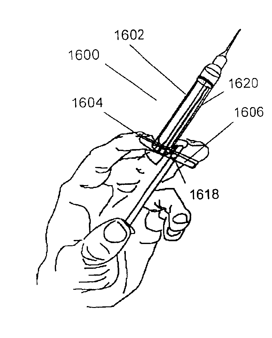
[0041]For the purposes of the present invention, the term “reciprocating member” refers to plungers, sliders, thumb rest mounted on a belt, plunger with teeth on one side, etc., which is connected to a syringe plunger by a reciprocating device and moves in a direction opposite a direction of motion of the syringe plunger to which the reciprocating member is connected.

[0042]For the purposes of the present invention, a “reciprocating device” refers to a device which combines the functions of connecting a syringe plunger t...


PUM


Abstract

The present invention provides a syringe device comprising: a first syringe comprising: a first syringe barrel including a first opening at a distal end thereof through which fluid may be forced or aspirated; and a first syringe plunger sliding within the first syringe barrel for forcing fluid through the first syringe barrel opening, the first syringe plunger including a stopper at a distal end thereof which sealingly and slidably engages the first syringe barrel; a reciprocating member which moves along a track parallel to the axial direction of the first syringe; and a reciprocating device connecting the first syringe plunger to the reciprocating member so that when one member of the group consisting of the first syringe plunger and the reciprocating member moves distally, the other member of the group is forced to move proximally. The present invention also provides a syringe device where one member of the group consisting of the first syringe plunger and the reciprocating member moves proximally, the other member of the group is forced to move distally.

Description

CROSS-REFERENCE TO RELATED APPLICATION[0001]The present application is a divisional of and claims the priority of U.S. patent application Ser. No. 09 / 303,555, entitled “Reciprocating Syringes” filed May 3, 1999, now U.S. Pat. No. 6,245,046. The entire disclosure and contents of the above mentioned application is hereby incorporated by reference.BACKGROUND OF THE INVENTION[0002]1. Field of the Invention[0003]The present invention relates generally to single-handed syringe.[0004]2. Description of the Prior Art[0005]Syringes are an essential element in the day-to-day practice of medicine and nursing, but are also essential in industry, laboratory science, research, and animal husbandry. Syringes are used to inject medications, aspirate body fluids, provide vacuum, and transfer fluids. The syringe design most commonly used in medicine consists of a barrel made of plastic and an internal plunger which is moved into or out of the barrel, resulting in pressure or a vacuum, respectively. Th...

Claims


Application Information

Patent Timeline
IPC IPC(8): A61M5/19A61M5/31A61M5/315A61M5/00A61M5/28
CPCA61M5/284A61M5/3148A61M5/31511A61M5/19A61M2005/3152
Inventor SIBBITT, WILMER L.
Owner STC UNM
Why Eureka
Try Eureka