
Light diffusive sheet

a light diffusing sheet and light diffusion technology, applied in the field of light diffusion sheets, can solve the problems of reduced displaying quality, insufficient visibility, high production cost, etc., and achieve the effects of stable diffused light, improved light diffusion action, and improved light diffusion effect of the second light diffusion sh

Inactive Publication Date: 2005-11-08
TAKIRON CO LTD
View PDF21 Cites 29 Cited by
  • Summary
  • Abstract
  • Description
  • Claims
  • Application Information

AI Technical Summary

Benefits of technology

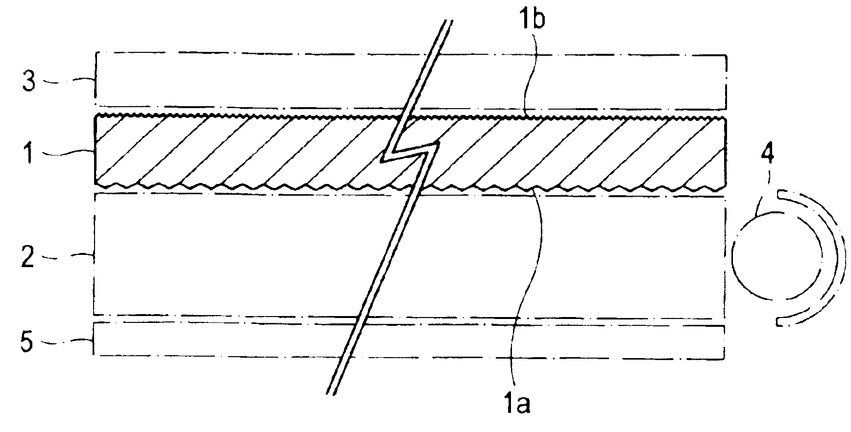
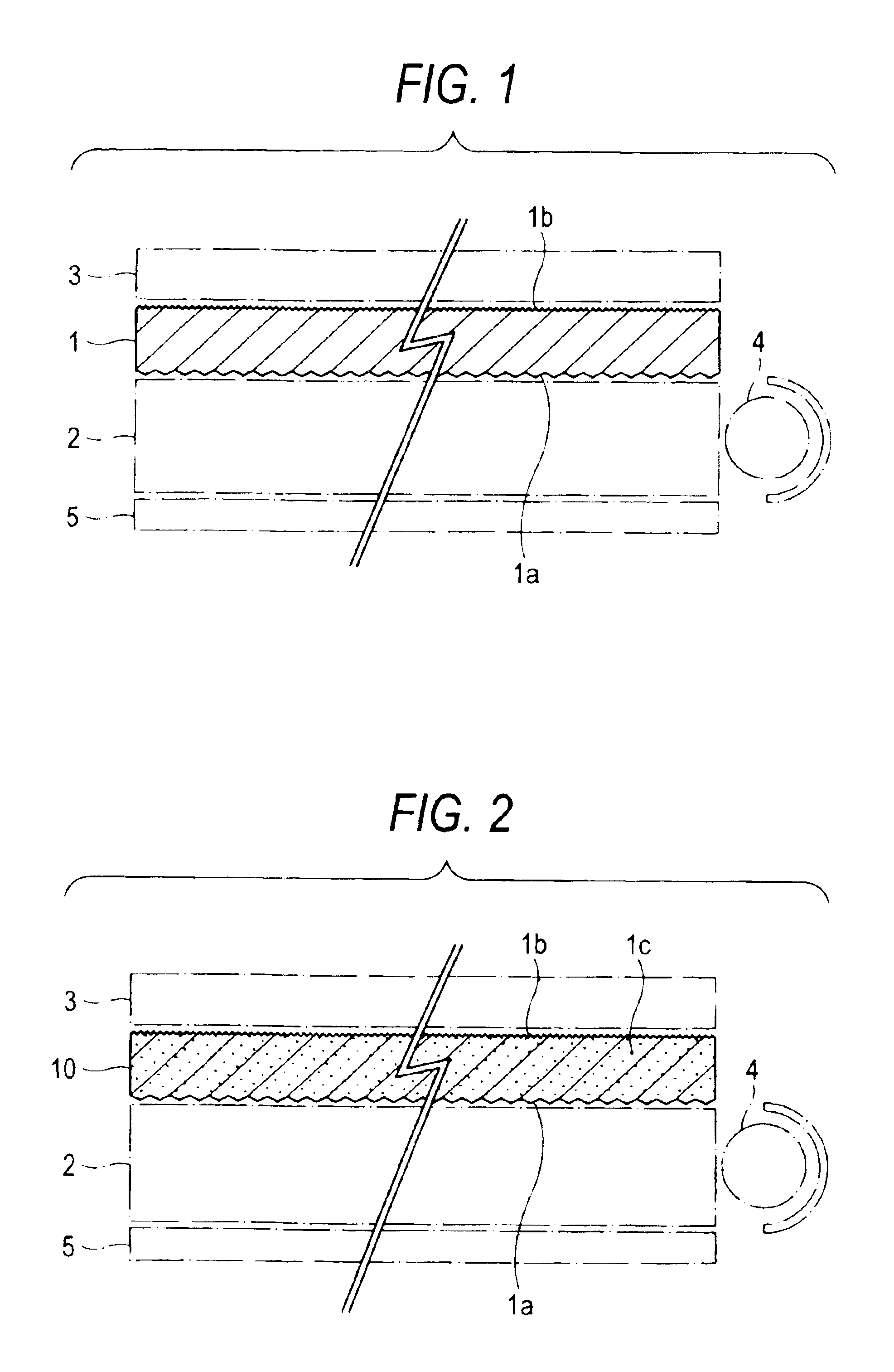
[0012]For emitting uniform diffused light having no variation of brightness by controlling optical loss to a small degree, it is necessary that a large quantity of light can enter easily into the sheet almost uniformly from one side of the light diffusing sheet and that the light-departing opposite side is excellent in light diffusion action. According to the first light diffusing sheet of the invention, difference of elevation of the irregularity on one side which becomes the light-entering side is larger than that of the irregularity of the opposite side, and distribution density of the irregularity is roughened at the same time, so that a large quantity of light can enter almost uniformly from said one side and interference and diffraction of light can be prevented at the same time, and on the other hand, by allowing difference of elevation of irregularity on the opposite side which becomes the light-departing side to distribute smaller and densely than that of the irregularity of the one side, light diffusion action of the opposite side is improved and optical loss is also reduced by returning the diffused light discharged into outside the panel again into inside of the panel.
[0014]According to the aforementioned light diffusing sheet, the light diffusion becomes more excellent, and more uniform diffused light can be discharged, when the average surface roughness of one side is controlled at from 0.3 to 3.0 μm, and the average surface roughness of the opposite side at from 0.3 to 1.5 μm, the surface area ratio of the one side at from 1.005 to 1.070 and the surface area ratio of the opposite side at from 1.010 to 1.200.
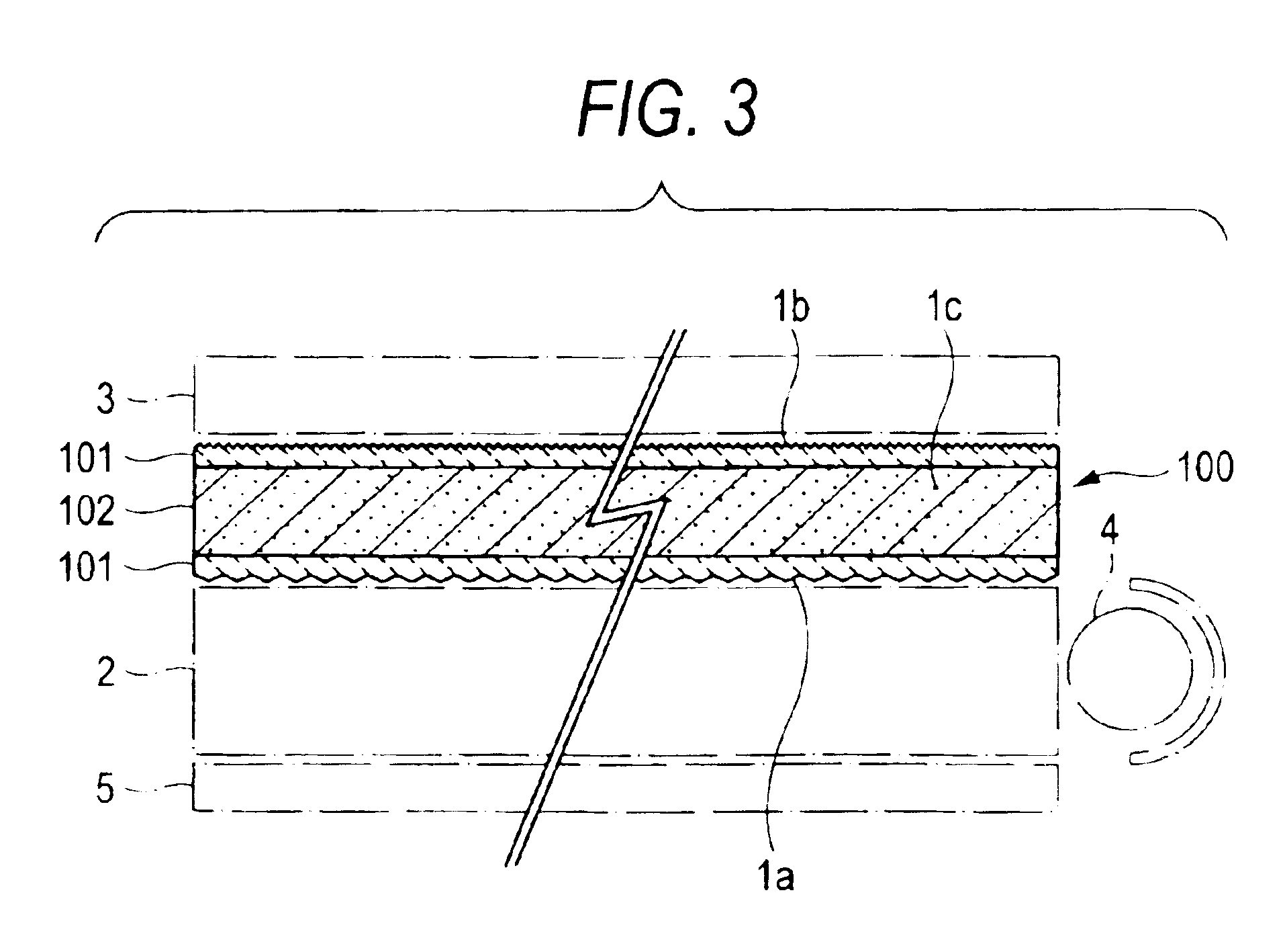
[0016]Since the light entered into the sheet from one side is diffused by the light diffusing agent, light diffusion action of this second light diffusing sheet is improved. Because of this, diffused light having no variation of brightness can be discharged through uniform and sufficient diffusion of light entered from a light introducing plate, when the average surface roughness of the one side which becomes the light-entering side of this light diffusing sheet is from 0.2 to 5.0 μm, and the average surface roughness of the opposite side that becomes the light-departing side is smaller than that of the aforementioned one side, which is within the range of from 0.2 to 2.0 μm. Also, expansion and contraction of the sheet become small due to the light diffusing agent and wrinkles are not generated on the sheet even when it is heated by light from the light source, so that uniform diffused light can be discharged stably.
[0017]The light diffusion becomes further excellent without causing inhibition of light transmission when the aforementioned light diffusing agent has a mean particle size of from 0.5 to 50 μm and is contained in the light-transmittable resin in an amount of from 0.1 to 50% by weight. Also, generation of wrinkles can be sufficiently inhibited through reduction of expansion and contraction of the sheet due to heat from the light source, so that stable diffused light can be obtained.
[0018]It is desirable that the surface area ratio of one side of the aforementioned second light diffusing sheet is from 1.001 to 1.150 and the surface area ratio of the opposite side is from 1.010 to 1.250, because the entering light becomes more uniform and variation of brightness of the diffused light also becomes further small.
[0019]Also, the aforementioned effects are further improved when the average surface roughness of the aforementioned one side is from 1.0 to 3.0 μm, the average surface roughness of the aforementioned opposite side is from 0.5 to 1.5 μm, the surface area ratio of the aforementioned one side is from 1.030 to 1.100 and the surface area ratio of the aforementioned opposite side is from 1.050 to 1.200.

Problems solved by technology

However, the light diffusing sheet of (1) had problems such as insufficient visibility, reduction of displaying quality, high production cost due to poor yield and the like, because the polymer beads or inorganic particulates protruding from the surface of light diffusing layer impair the lens film superposed thereon and are apt to fallout from the light diffusing layer by an impact and the like.
Also, though dispersing ability of the light diffusing sheet of (2) is improved by the irregularity formed on one side or both sides thereof, it had the same problems as those of the light diffusing sheet of (1) because a light diffusing layer containing particulates is arranged on its surface and, in addition, it had another problem of further increasing its production cost because it requires two processes of a irregularity forming process by embossing and a light diffusing layer forming process.
In addition, the light diffusing sheet of (3) had a problem in that when the irregular shape formed on the surface of one side or both sides is not appropriate, the light scattering becomes insufficient or the light scattering becomes heterogeneous to cause partial variation of the brightness or becomes visualization of dots on the light introducing plate face.
There was also a problem in that wrinkles are generated on the light diffusing sheet when it is heated by light and heat from the light source, thus resulting in uneven light scattering and varied brightness.

Method used


Image

  • Light diffusive sheet
  • Light diffusive sheet
  • Light diffusive sheet

Examples


##ventive example 1

Inventive Example 1

[0058]A light diffusing sheet having irregularities on both sides was prepared by extrusion-molding a polypropylene resin into a sheet of 110 μm in thickness and then passing it through upper and lower embossing rollers having different emboss sizes.

[0059]When center line average surface roughness Ra of the above light diffusing sheet was measured within a measuring range of 230.6×175.4 μm using a WYKO surface shape measuring apparatus NT-2000 (mfd. by WYKO), the average surface roughness Ra of one side which becomes the plane of incidence was 0.445 μm and the average surface roughness Ra of the opposite side which becomes light-departing plane was 0.305 μm.

[0060]Also, when surface area ratio (S / S0) was calculated by measuring surface area of the above light diffusing sheet within a measuring range of 400×400 μm using a probe microscope (using Nanopics 1000 controller and NPX 100 head mfd. by Seiko Instruments), surface area ratio of the one side was 1.0064 and su...

##ventive example 2

Inventive Example 2

[0063]A light diffusing sheet having irregularities on both sides was prepared in the same manner as in Inventive Example 1, except that upper and lower embossing rollers having emboss sizes different from those of the embossing rollers of Inventive Example 1 were used.

[0064]When average surface roughness Ra, surface area ratio (S / S0), total light transmittance, haze value, brightness and dot concealing property of this light diffusing sheet were measured in the same manner as in Inventive Example 1, the average surface roughness Ra of one side which becomes the light-entering side was 0.642 μm, the average surface roughness Ra of the opposite side which becomes light-departing side was 0.322 μm, the surface area ratio of the one side was 1.0077, the surface area ratio of the opposite side was 1.0385, the total light transmittance was 95.1%, the haze value was 64.5%, the brightness was 96.4 cd / m2 and the dot concealing property was good.

[0065]Measured results of t...

##ventive examples 3 to 8

Inventive Examples 3 to 8

[0077]Light diffusing sheets having irregularities on both sides of each sheet were prepared by adding silica light diffusing agents having mean particle diameters of 4 μm and 8 μm (Sylophobic 505 and 4004, mfd. by Fuji Silysia Kagaku) to the polypropylene resin used in Inventive Example 1 in respective amounts of 1.5% by weight, 2.5% by weight, 5% by weight and 10% by weight as shown in the following Table 2, uniformly mixing them, and then extrusion-molding the mixture into a sheet of 110 μm in thickness using embossing rollers different from the embossing rollers used in Inventive Example 1. In this case, as Comparative Example 5, a light diffusing sheet having the same thickness but not containing the above light diffusing agent was prepared using the same embossing rollers.

[0078]Total light transmittance and haze value of these light diffusing sheets were measured in the same manner as in Inventive Example 1, and average surface roughness and surface ar...


PUM

PropertyMeasurementUnit
surface roughnessaaaaaaaaaa

Abstract

The invention provides a sheet (1) comprising a light-transmittable resin, in which irregularities are formed on both sides (1a) and (1b) of the sheet, the average surface roughness of one side (1a) which becomes the light-entering side is from 0.2 to 5.0 μm and larger than the average surface roughness of the opposite side (1b) that becomes the light-departing side, wherein the average surface roughness of the opposite side (1b) is from 0.2 to 2.0 μm, and the surface area ratio of the one side (1a) is smaller than the surface area ratio of the opposite side (1b).

Description

TECHNICAL FIELD[0001]This invention relates to a light diffusing sheet which is used in liquid crystal display back light units, decorative illumination sign boards, illumination covers, arcades, lighting board, balcony screen boards and the like.BACKGROUND OF THE INVENTION[0002]General back light unit of liquid crystal display is constructed by a light introducing plate having dots for light diffusion which are printed on its reverse side, a light source (a cold-cathode tube or the like) arranged on one side or both sides of this light introducing plate, a light diffusing sheet superposed on this light introducing plate, a lens film (prism sheet) superposed on this light diffusing sheet or on above and below thereof, and the like.[0003]As such light diffusing sheets, (1) a sheet in which a light diffusing layer containing polymer beads or inorganic particulates as a light diffusing agent is arranged on at least one side of a transparent base material (Japanese Patent No. 2,665,301)...

Claims


Application Information

Patent Timeline
Patent Type & Authority Patents(United States)
IPC IPC(8): G02B5/02
CPCG02B5/0221G02B5/0268G02B5/0278G02B5/02
Inventor SE, KOICHIOMURA, YUTAKA
Owner TAKIRON CO LTD
Learn More