Adaptive fuel injector trimming during a zero fuel condition

a fuel injector and zero fuel condition technology, applied in the field of fuel injector trimming, can solve the problem of high undesirable emissions requirements

Inactive Publication Date: 2005-11-15
PERKINS ENGINES
View PDF14 Cites 76 Cited by
  • Summary
  • Abstract
  • Description
  • Claims
  • Application Information

AI Technical Summary

Problems solved by technology

Inconsistency in the amount of fuel delivered can lead to higher undesirable emissions requirements than if the fuel injector was calibrated.

Method used


Image

  • Adaptive fuel injector trimming during a zero fuel condition
  • Adaptive fuel injector trimming during a zero fuel condition
  • Adaptive fuel injector trimming during a zero fuel condition

Examples


Embodiment Construction

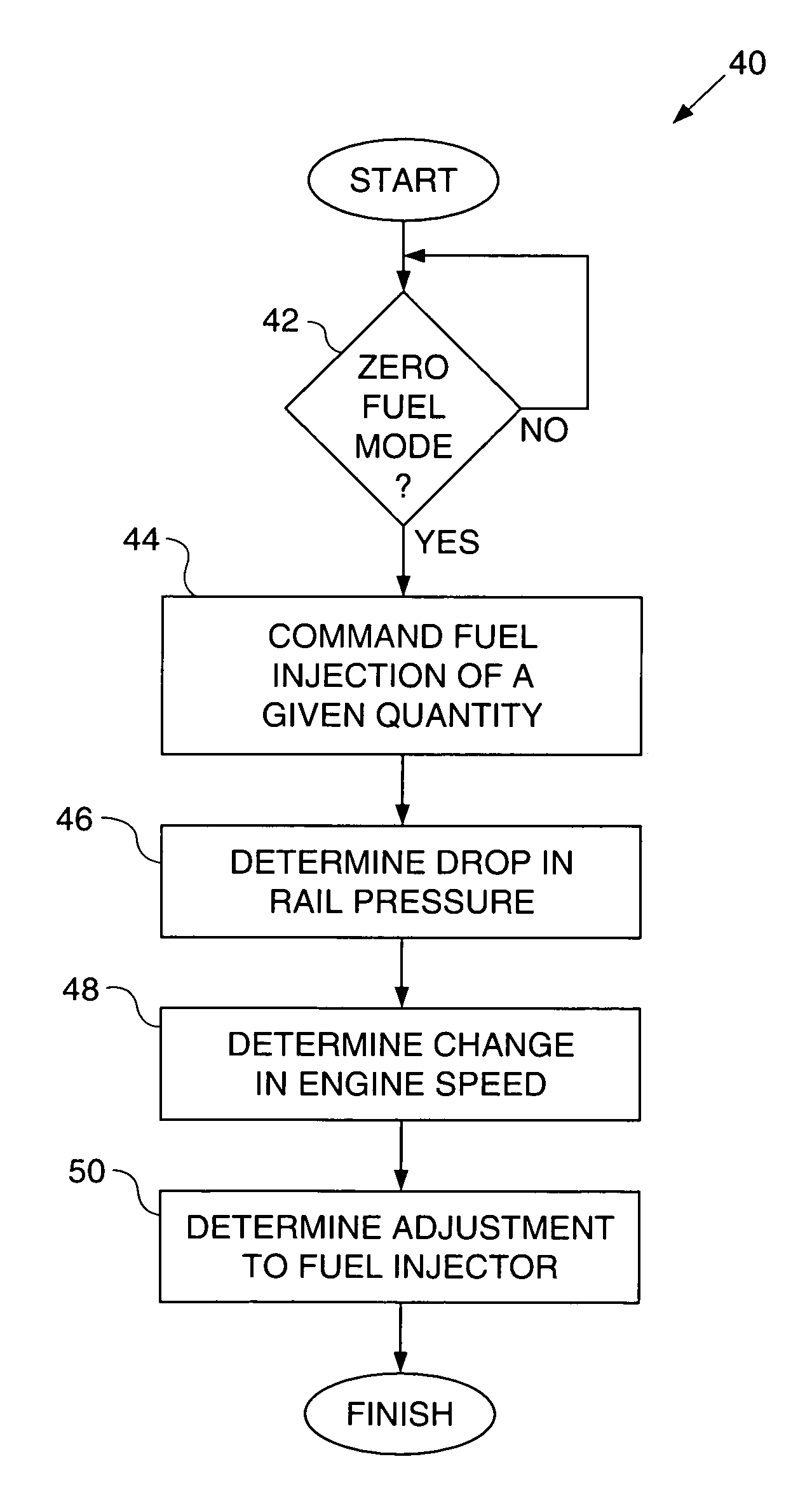
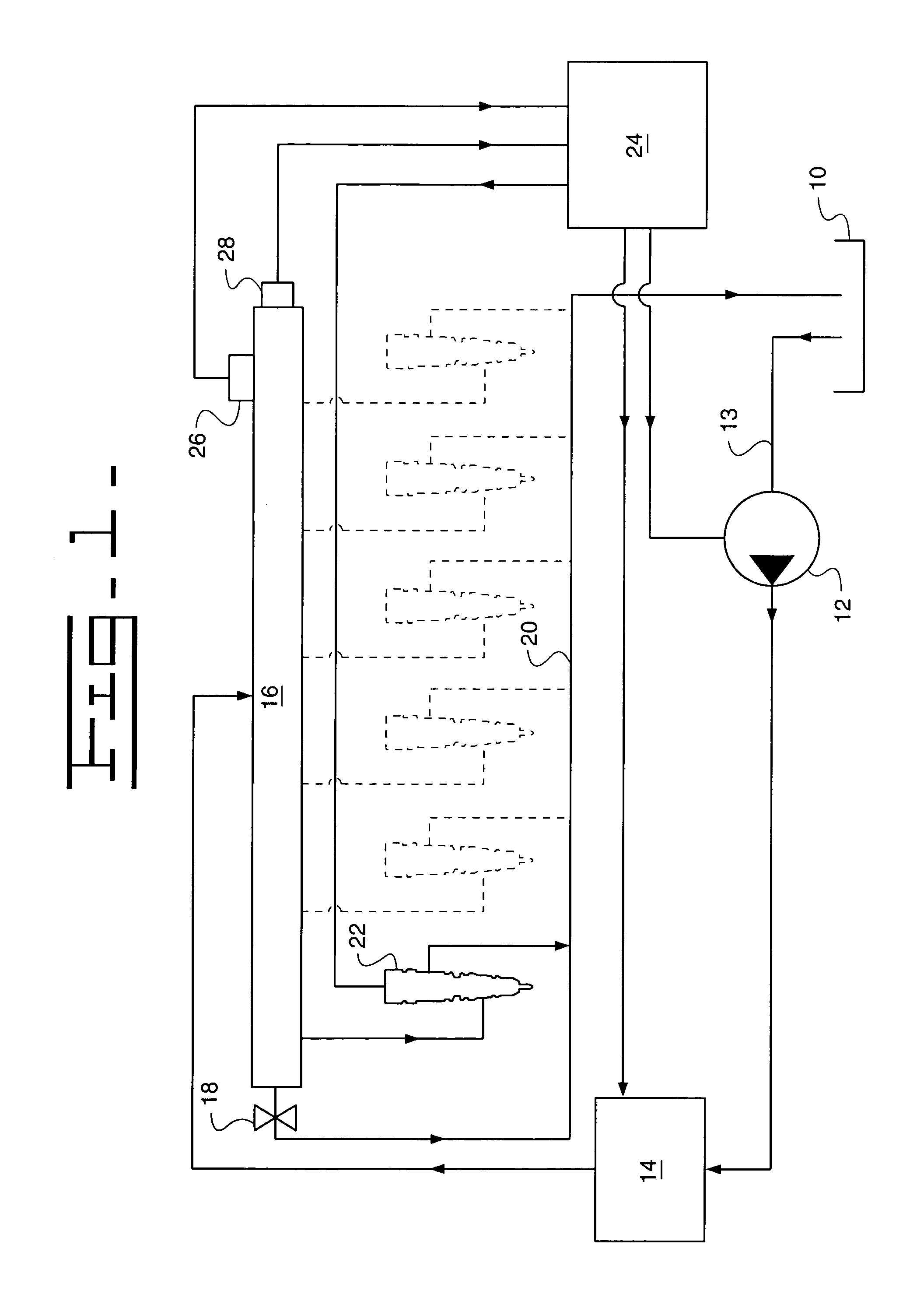
[0009]Referring to FIG. 1, a fuel system utilizing a common rail fuel injector 22 according to one embodiment of the invention is shown. Although for exemplary purposes, the discussions herein describe a common rail fuel injector, the invention may apply equally to other types of fuel injectors. A reservoir 10 contains fuel at an ambient pressure. A transfer pump 12 draws low-pressure fuel through fuel supply line 13 and provides it to high-pressure pump 14. High-pressure pump 14 then pressurizes the fuel to desired fuel injection pressure levels and delivers the fuel to fuel rail 16. The pressure in fuel rail 16 is controlled in part by safety valve 18, which spills fuel to the fuel return line 20 if the pressure in rail 16 is above a desired pressure. The fuel return line 20 returns fuel to low-pressure reservoir 10.

[0010]Fuel injector 22 draws fuel from rail 16 and injects it into a combustion cylinder of the engine (not shown) by ways known to those skilled in the art. Fuel not ...


PUM


Abstract

Apparatuses and methods for controlling a fuel injector. A fuel shot is injected during a zero fuel condition. A rail pressure drop corresponding to the fuel shot is determined. A change in engine speed corresponding to the fuel shot is determined. An adjustment to the fuel injection as a function of the rail pressure drop and the corresponding change in engine speed is determined.

Description

TECHNICAL FIELD[0001]This invention relates generally to a fuel injector, and more specifically, to the trimming of fuel injectors.BACKGROUND[0002]Electronically controlled fuel injectors are known to change over time in fuel injection quantity for a given injector signal on-time. Inconsistency in the amount of fuel delivered can lead to higher undesirable emissions requirements than if the fuel injector was calibrated.[0003]One potential solution to this problem is the periodic recalibration of the fuel injector during routine servicing. Relying on this approach, however, is dependent on the routine servicing actually occurring, and occurring at an interval-that is shorter than that which allows the fuel injector to substantially deviate from its initial fuel injection characteristics.SUMMARY OF THE INVENTION[0004]The present invention provides apparatuses and methods for controlling a fuel injector. A fuel shot is injected during a zero fuel condition. A rail pressure drop corresp...

Claims


Application Information

Patent Timeline
Patent Type & Authority Patents(United States)
IPC IPC(8): F02D41/12F02D41/00F02D41/24F02D41/38
CPCF02D41/123F02D41/2438F02D41/2441F02D41/247F02D41/3809F02D2041/224F02D2200/0602F02D2200/1012
Inventor WARNE, DAVID G.RENSHAW, JOHN
Owner PERKINS ENGINES
Why Eureka
Try Eureka