
Screen panel retainer system

a technology of screen panel and retainer, which is applied in the direction of screening, solid separation, chemistry apparatus and processes, etc., can solve the problems of requiring the services of technicians, inevitably taking time for modification or re-fitting, and meeting resistan

Inactive Publication Date: 2005-11-15
CONN WELD IND
View PDF8 Cites 25 Cited by
  • Summary
  • Abstract
  • Description
  • Claims
  • Application Information

AI Technical Summary

Benefits of technology

"The present invention provides a screen panel retainer system for a vibrating separatory machine that can securely hold screen panels in place without requiring modifications to the machine. The system includes elongated panel retainer bars with self-expanding retainer pins that can accommodate variations in hole sizes in screen stringer rails. The system also includes dams to slow down the flow of material being separated and plugs that can expand radially to securely fit into the screen stringer rail holes. The system can be used with various vibrating separatory machines while requiring no modification to the machines. The plugs are made of a resilient material, such as polyurethane, and are securely held in place by the interference fit with the screen stringer rail holes. The system also includes a screen panel retainer that can be easily installed and removed."

Problems solved by technology

Such modifications or re-fittings inevitably take time, require the services of technicians and meet with resistance on the part of equipment owners who want to purchase screen panels and panel retainers that will fit the machinery they already have, without the need for any modification, revision, re-working or equipment downtime.
Over the course of time, the slurry abrades the holes and causes them to enlarge.
Since a number of the currently available panel retainer systems utilize some type of an interference fit of pins, pegs or the like into these holes, their enlargement is problematic.
At some point, the stringer bar holes become so enlarged that they will no longer engage the pins or pegs with sufficient retentive force.
In each instance, the process involves considerable work and the equipment being taken out of service.

Method used


Image

  • Screen panel retainer system
  • Screen panel retainer system
  • Screen panel retainer system

Examples


Embodiment Construction

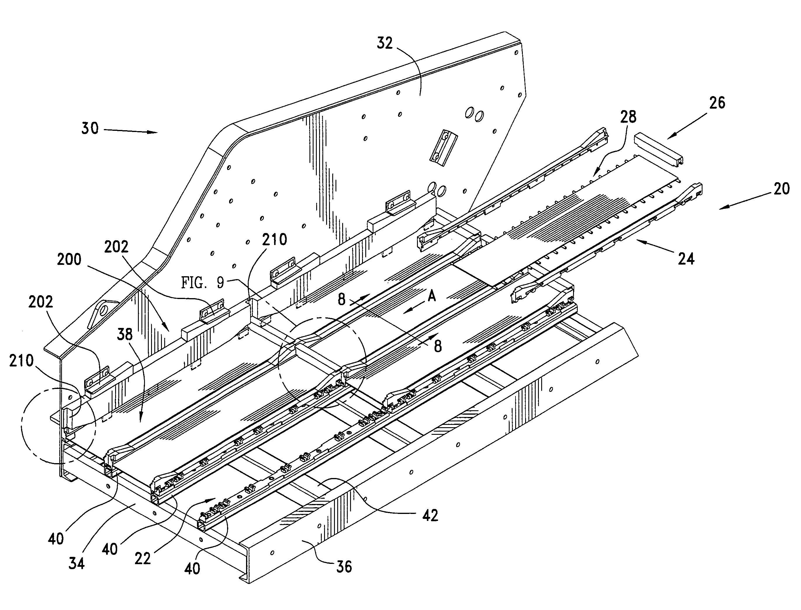
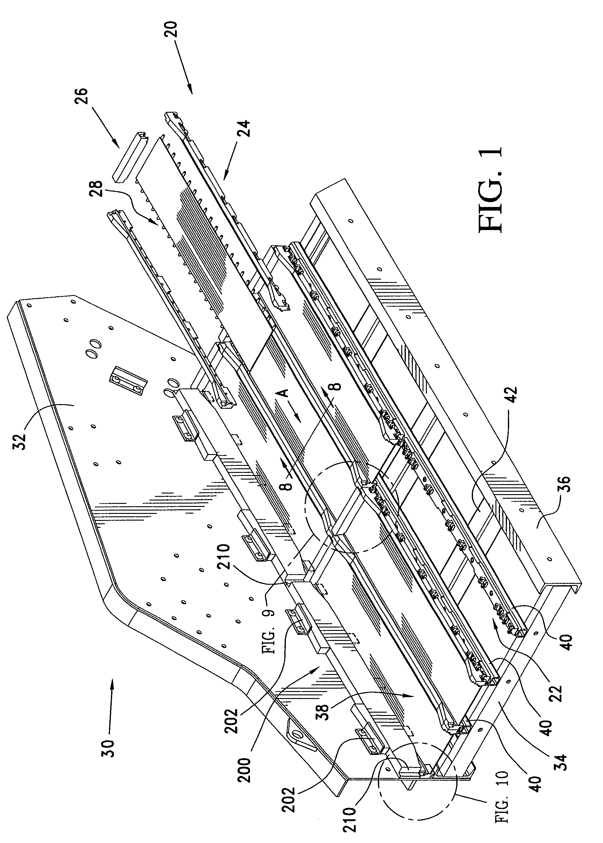
[0037]Referring initially to FIG. 1, there may be seen generally at 20 a preferred embodiment of a screen panel retainer system in accordance with the present invention. Screen panel retainer system generally at 20 includes elongated retainer bars, generally at 22, which are adapted to receive screen edge strips 24 and to also receive end dams 26. These retainer bars 22, edge strips 24 and end dams 26 form a retainer system intended to removably attach screen panels, such as screen panel 28 to a vibrating separatory machine, that is depicted somewhat schematically at 30 in FIG. 1. It will be understood that the vibrating separatory machine 30 depicted in FIG. 1 is representative of various machines of this type which are provided by a variety of manufacturers and which are used in numerous industrial applications to classify and separate particulate matter, typically in the form of a slurry of particles and water. Such vibrating separatory machines 30 typically include a pair of sid...


PUM


Abstract

A screen panel retainer system is useable to retain a plurality of screen panels to a separatory machine. Retainer bars are attached to the screen stringer rails of the separatory machine by an expanding of spaced plugs that are received in holes in the stringer rails. The retainer bars each include a plurality of ears that are receivable in pockets that are situated on the inner faces of screen panel edge strips. A plurality of dams, each of which is securable to the screen edge strip ends of two adjacent screen panels, serve to further secure the screen panels in place. Screen panel removal is easily accomplished and the system is adaptable to various machine configurations.

Description

FIELD OF THE INVENTION[0001]The present invention is directed generally to a screen panel retainer system. More particularly, the present invention is directed to a screen panel retainer system for use in securing screen panels to a frame of a vibrating separatory device. Most specifically, the present invention is directed to a screen panel retainer system that utilizes elongated retainer bars, including self-expanding retainer pins and screen panel edge engaging ears, which are receivable in cooperatively shaped pockets in screen panel edge strips. The retainer pins on the elongated retainer bars are spaced to be receivable in the spaced holes or apertures which are typically situated on the upper surface of screen stringer rails provided in vibrating separatory machines. The retainer pins are expandable to securely hold the retainer bars in place and to thus retain the screen panels. The retainer bar ears releasably receive the screen panel edge strips. The screen panel retainer ...

Claims


Application Information

Patent Timeline
Patent Type & Authority Patents(United States)
IPC IPC(8): B07B1/00B07B1/46
CPCB07B1/46B07B1/4609B07B2201/02
Inventor BACHO, FRANK J.CONNOLLY, JAMES D.
Owner CONN WELD IND
Learn More