Recording tape cartridge

a technology of tape cartridges and tape sleeves, which is applied in the field of tape cartridges, can solve the problems of complex structure of drive devices, and increased width of leader blocks 208, and achieves the effect of simple operation and compactness

Inactive Publication Date: 2005-11-15
FUJIFILM HLDG CORP +1
View PDF5 Cites 24 Cited by
  • Summary
  • Abstract
  • Description
  • Claims
  • Application Information

AI Technical Summary

Benefits of technology

[0016]In view of the aforementioned, an object of the present invention is to provide a recording tape cartridge which is provided with a leader portion held by a pull-out means of a drive device by a simple operation of the pull-out means, and which aims to make the leader portion more compact.
[0020]Here, the leader portion is merely nipped by the pull-out device from the top and bottom of the leader portion which are exposed to the exterior of the case. Thus, it suffices for the pull-out device to nip the leader portion after the pull-out device has reached positions above and below the exposed cutout portions (i.e., has reached the nipping positions). Namely, the leader portion is held by the pull-out device by a simple operation of the pull-out device. Further, at the leader portion which is simply nipped from above and below, there is no need to form a large engaging concave portion (a large-diameter concave portion) as in the conventional art. Thus, the width of the leader portion can be made smaller.
[0021]In this way, the recording tape cartridge of the present invention is provided with the leader portion which is held by a pull-out device of a drive device by simple operation of the pull-out device. Further, in the recording tape cartridge, the leader portion can be made compact.
[0022]Further, the recording tape cartridge having the above-described structure may be provided with a shutter which usually closes the opening and the cut-out portions, and which opens the opening and the cut-out portions at the time when the recording tape is to be pulled out. In this structure, there is no need for the leader portion to bear the function of closing the opening, and the leader portion can be made even more compact.

Problems solved by technology

Accordingly, a problem arises in that the width of the leader block 208 increases.
Moreover, the opening width of the fit-in portion of the aforementioned reel hub must be made large, and this is a cause of a step arising at the take-up surface.
The operation of this pull-out means is complex.
In this way, in a conventional recording tape cartridge equipped with a leader pin, the structure of the drive device is complex.

Method used


Image

  • Recording tape cartridge
  • Recording tape cartridge
  • Recording tape cartridge

Examples


Embodiment Construction

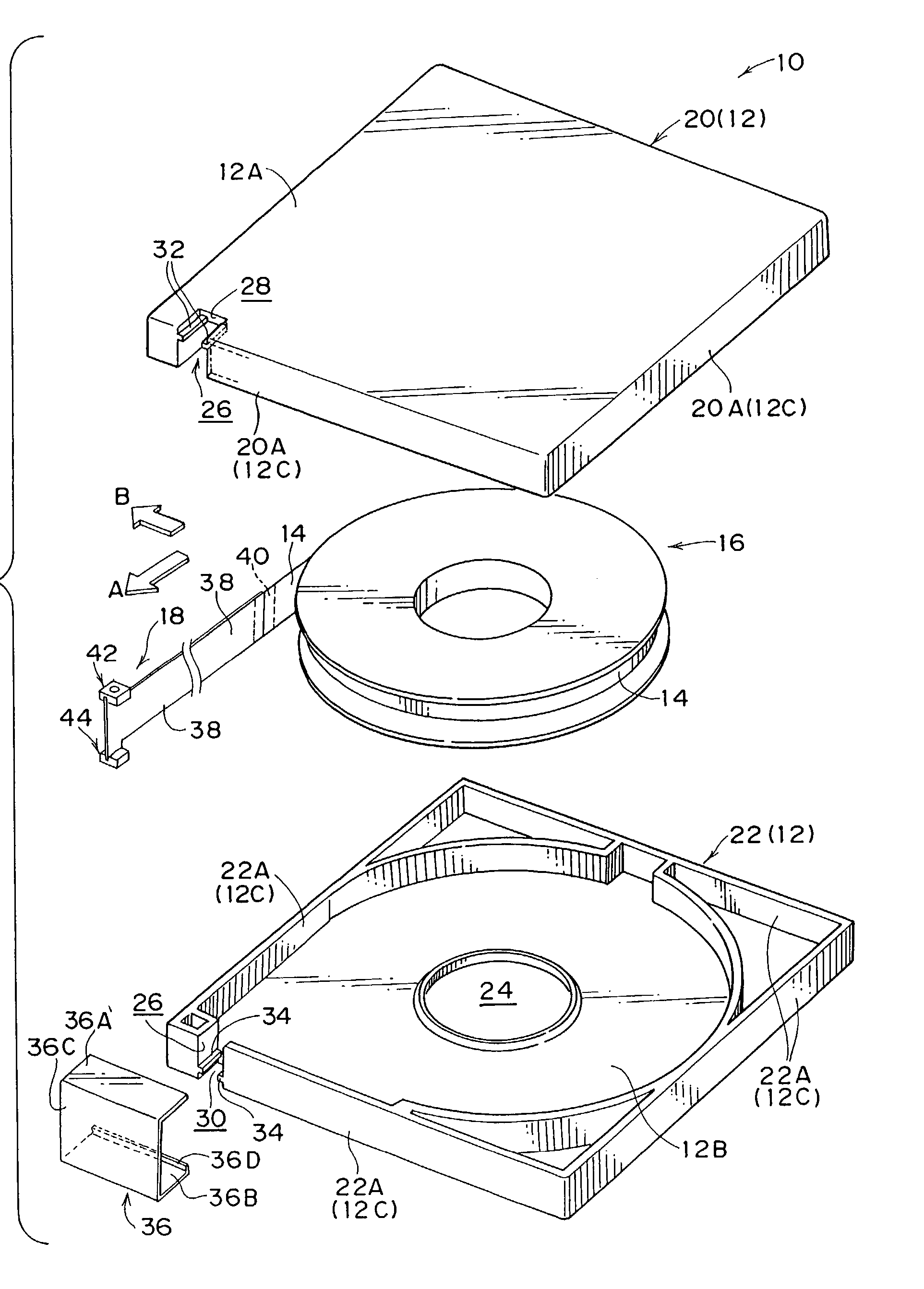
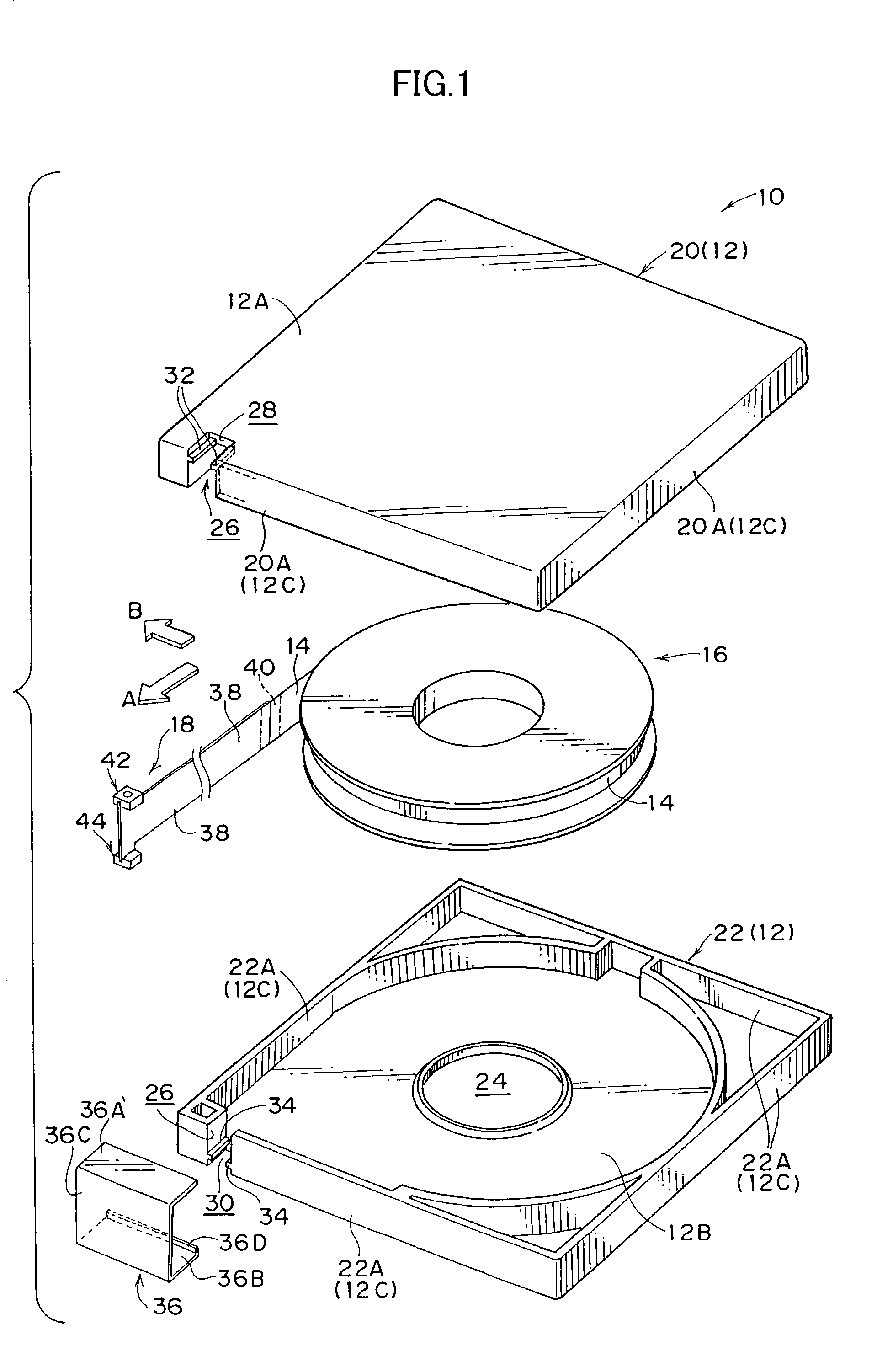
[0039]A recording tape cartridge 10 relating to an embodiment of the present invention will be described hereinafter with reference to FIGS. 1 through 9. Note that, for convenience of explanation, arrow A shown in FIG. 1 as well as other figures denotes the direction of loading the recording tape cartridge 10 into a drive device 50. For convenience, this loading direction will be referred to as the front direction, and the direction of arrow B, which is orthogonal to the direction of arrow A, is the rightward direction.

[0040]The schematic overall structure of the recording tape cartridge 10 is shown in perspective view in FIG. 1. The recording tape cartridge 10 is structured such that a single reel 16, on which is wound a magnetic tape 14 serving as a recording tape which is an information recording / playback medium, is rotatably accommodated within a case 12 which is substantially rectangular in plan view. Further, a leader portion 18 is provided at the distal end of the magnetic ta...


PUM

PropertyMeasurementUnit
thicknessaaaaaaaaaa
thicknessaaaaaaaaaa
widthaaaaaaaaaa

Abstract

A recording tape cartridge rotatably accommodating, within a case, a reel on which a recording tape is wound. A leader portion is provided at a distal end of the recording tape. The leader portion has a leader tape connected to the recording tape, and holding blocks provided at vertical direction outer sides of a distal end of the leader tape. In a state in which the holding blocks are held so as to face an opening of the case, the holding blocks are exposed from cut-out portions. Due to the holding blocks being nipped and held by a guiding mechanism of a drive device and the guiding mechanism moving, the holding blocks are separated from the case.

Description

BACKGROUND OF THE INVENTION[0001]1. Field of the Invention[0002]The present invention relates to a recording tape cartridge which rotatably accommodates a single reel on which a recording tape, such as a magnetic tape or the like, is wound.[0003]2. Description of the Related Art[0004]Recording tapes such as magnetic tapes and the like are used as external recording media for computers and the like. The recording surface area of a recording tape is large, and the recording tape is used mainly for back-up of a large quantity of information. Thus, it is desirable to prevent dust from adhering to the recording tape, and for the space for accommodating the recording tape at the time of storage thereof to be small.[0005]Thus, a recording tape cartridge, in which a recording tape is wound on a single reel and which rotatably accommodates the reel within a case, is used. In this way, owing to the case, dust can be prevented from adhering to the recording tape. Moreover, the accommodating sp...

Claims


Application Information

Patent Timeline
Patent Type & Authority Patents(United States)
IPC IPC(8): G11B23/107G11B23/08
CPCG11B15/674G11B23/107
Inventor HIRAGUCHI, KAZUO
Owner FUJIFILM HLDG CORP
Why Eureka
Try Eureka