
Ink-jet recording apparatus and recording method thereof

a recording apparatus and inkjet technology, applied in the direction of printing, other printing apparatus, etc., can solve the problems of paper jams, staining on the other sheet of recording paper, and likely to collide with the wall of the large hole, so as to prevent the removal of ink-absorbing materials, easy to form, and easy to be used

Inactive Publication Date: 2005-11-15
SEIKO EPSON CORP +1
View PDF28 Cites 55 Cited by
  • Summary
  • Abstract
  • Description
  • Claims
  • Application Information

AI Technical Summary

Benefits of technology

This solution effectively prevents ink adhesion and staining, maintains high print quality by minimizing ink wastage and airborne mist, and reduces the risk of paper jams, enabling reliable margin-free printing.

Problems solved by technology

The ink which has adhered to the platen adheres to another sheet of recording paper, thus making a stain on the other sheet of recording paper.
However, presence of the large hole makes the leading edge of recording paper supplied by a paper feed roller (which may also be called a roller for feeding the recording medium) likely to collide with the wall of the large hole.
In the event of such a collision, a so-called paper jam is likely to arise at this location.
Further, the presence of a large hole results in the platen encountering difficulty in firmly supporting recording paper in a position opposite the nozzle array, thereby resulting in a change in the distance between the recording head and the recording paper.
Consequently, print quality is deteriorated.
These problems arise even in a case where data are printed without leaving an end margin on recording paper.
The problems solved by the printer are elimination of non-coated areas from a tape during a solid coating process and staining of a recording medium to be transported, which would otherwise be caused when the ink droplets squirted during the solid coating process adhere to a guide member or a like member.
However, the printer of the background art fails to refer to or even suggest lateral-margin-free printing of text data.
However, the ink recovery means is not designed in consideration of preventing minute staining of paper edges, which would otherwise be caused by airborne ink mist stemming from discarded ink droplets.
Hence, in a case where ink droplets are squirted over a long distance, airborne ink mist is likely to arise.
Further, in a case where paper is carried while being laid on a mesh screen or a like component, a portion of ink collides with not perforations of the mesh screen but with the framework of the mesh screen, also causing airborne ink mist.
An ink-jet recording apparatus capable of effecting printing of photographic quality is highly susceptible to influence of deterioration of print quality stemming from airborne ink mist.

Method used


Image

  • Ink-jet recording apparatus and recording method thereof
  • Ink-jet recording apparatus and recording method thereof
  • Ink-jet recording apparatus and recording method thereof

Examples


first embodiment

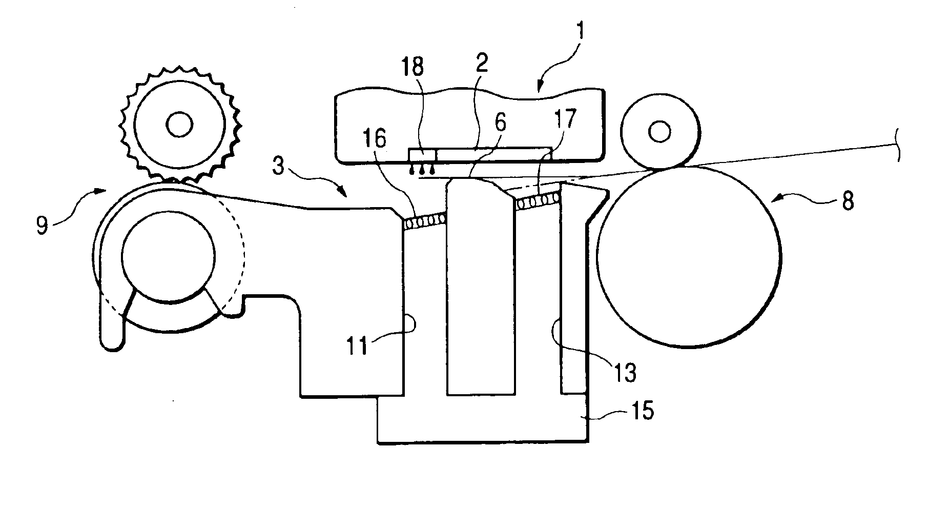
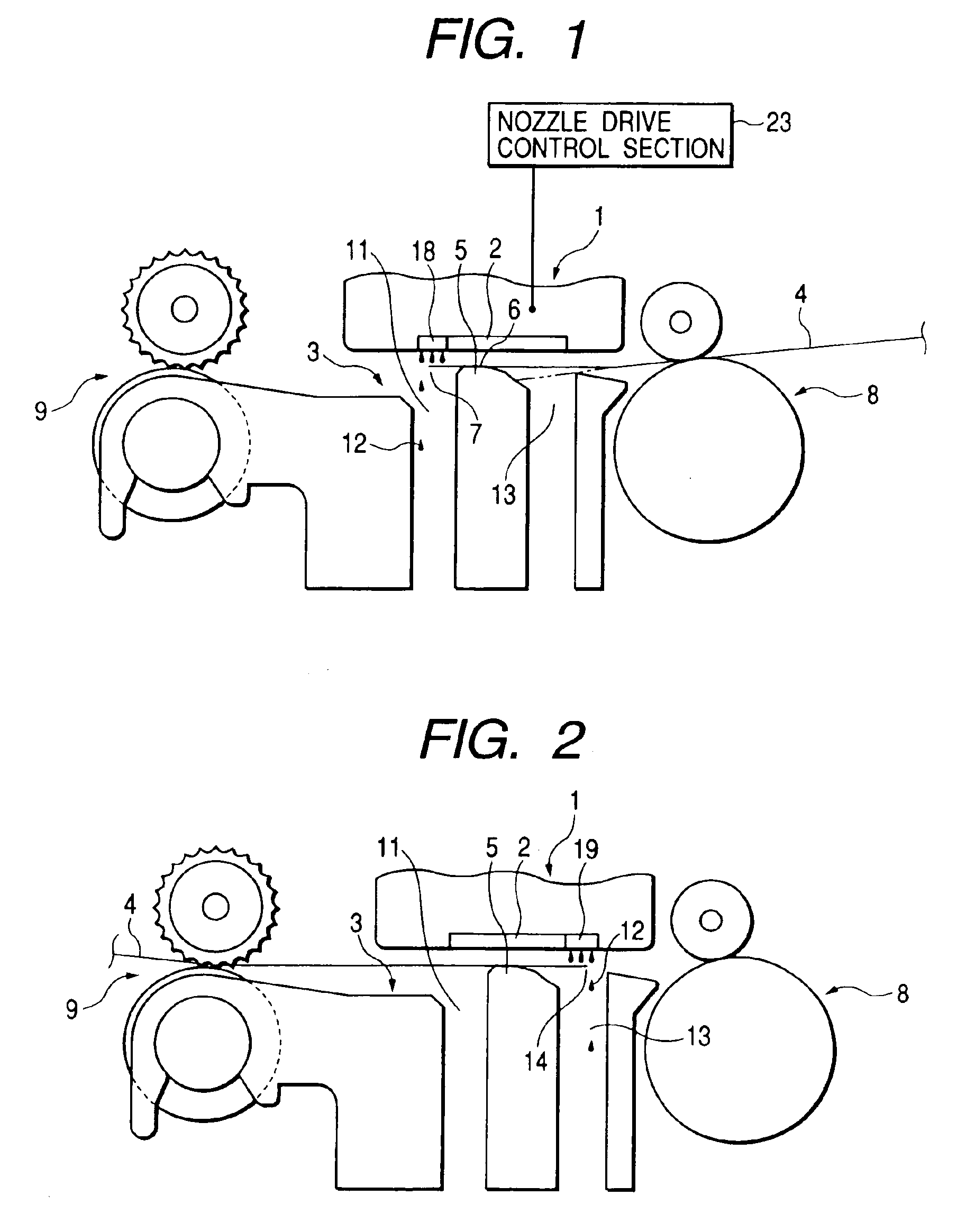
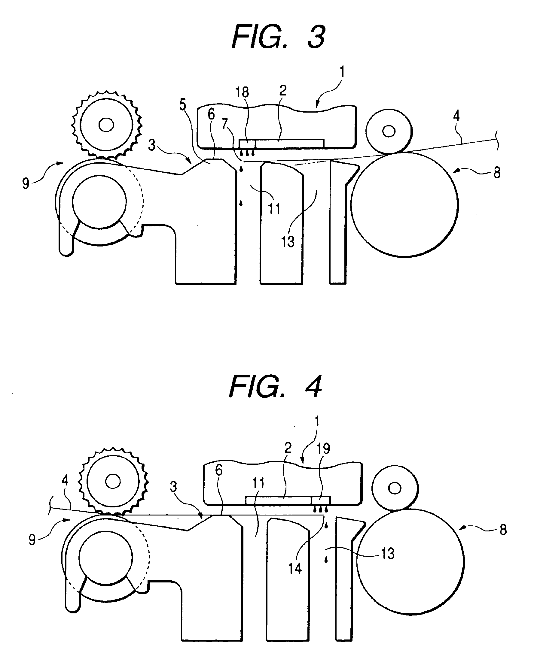
[0185]Preferred embodiments of the present invention will now be described by reference to the accompanying drawings. FIG. 1 shows an ink-jet recording apparatus according to the present invention; that is, FIG. 1 shows a cross-sectional view of the principal section of the recording apparatus when data are recorded on recording paper without leaving a margin on the top end of the paper. FIG. 2 is a cross-sectional view of the principal section of the ink-jet recording apparatus when data are recorded on the recording paper without leaving a margin on the bottom end of the paper.

[0186]As shown in FIG. 1, in the present embodiment, a first hole 11 is formed in a portion of the surface of a platen 3 opposite a downstream-side portion of a nozzle array 2 in a secondary-scanning direction. When data are recorded on recording paper 4 without leaving a margin on a top end 7 of the paper 4, the first hole 11 functions to receive all ink droplets 12 squirted outside the top end 7 of the pap...

second embodiment

[0275]The removable engagement section 55 of the paper support 51 can also be attached to the removable receiving section 21 of the sheet feeder 3. In the second embodiment, the roll-of-paper holder 25 is formed so as to be able to connect with the sheet feeder 3, by utilization of the removable receiving section 21 of the sheet feeder 3 for removably receiving the paper support 51. In other words, the removable receiving section 21 formed in the sheet feeder 3 can serve as an attachment point for both the roll-of-paper holder 25 and the paper support 51.

[0276]A withdrawable extension support 59 is provided on the reverse side of the upper end of the paper support 51. In a case where a single sheet of cut paper extends beyond the paper support 51, the extension support 59 is withdrawn supplementally, thus supporting the entirety of the single sheet of cut paper.

[0277]Next, the operation of the paper feeder according to the second embodiment of the invention shown in FIG. 48 will now...


PUM


Abstract

A recording apparatus has a recording head, a platen and a first hole. The recording head includes a dot formation element array, and the platen holds a recording medium opposite the recording head. The first hole is disposed in an area of the platen opposite a downstream portion of the dot formation element array and guides ink discarded outside an end of the recording medium when the end is printed without a margin. Alternatively or additionally, a second hole is formed in an area of the platen opposite an upstream portion of the dot formation element array, and the platen guides ink, which is discarded outside an end of the recording medium when the end is printed without a margin, too the second hole.

Description

FIELD OF THE INVENTION[0001]The present invention relates to an ink-jet recording apparatus, and more particularly, to an ink-jet recording apparatus having the function of recording without leaving blank space on at least one of the areas above, below, and on either side of a recording medium, as well as to a recording method for use with the apparatus.BACKGROUND OF THE INVENTION[0002]An example structure of a presently-known platen of an ink-jet recording apparatus will now be described. The ink-jet recording head has a dot formation element array (hereinafter referred to as a “nozzle array”) in which a plurality of dot formation elements (hereinafter referred to as “nozzles”) are arranged in a secondary scanning direction. A platen is provided opposite the recording head and functions to hold recording paper in position during a recording operation performed by a printer. A plurality of ribs are provided on the surface of the platen at given intervals in the primary scanning dire...

Claims


Application Information

Patent Timeline
Patent Type & Authority Patents(United States)
IPC IPC(8): B41J11/00B41J11/08B41J11/06B41J11/02B41J2/185
CPCB41J2/185B41J11/0065B41J11/06B41J11/08B41J29/02B41J2002/1742B41J2/1742
Inventor KODAMA, HIDETOSHIYOKOYAMA, KOICHIROKOMURO, KIYOTOYASUE, TAKUYAAKAHANE, TAKASHI
Owner SEIKO EPSON CORP
Learn More