Polyaxial bone screw locking mechanism

a locking mechanism and bone screw technology, applied in the field of bone screw, can solve the problems of not always being able to insert a bone screw, slipping under high loading, and requiring many parts, and achieve the effect of facilitating use and resisting the relative movement of the ball

Inactive Publication Date: 2005-11-15
JACKSON
View PDF49 Cites 257 Cited by
  • Summary
  • Abstract
  • Description
  • Claims
  • Application Information

AI Technical Summary

Problems solved by technology

When the head and shank of the bone screw are fixed in position relative to each other, it is not always possible to insert a bone screw in such a manner that the head will be in the best position for receiving other implants.
Unfortunately, the prior art devices have a tendency to be bulky, slip under high loading or require many parts.

Method used


Image

  • Polyaxial bone screw locking mechanism
  • Polyaxial bone screw locking mechanism
  • Polyaxial bone screw locking mechanism

Examples


Embodiment Construction

[0022]As required, detailed embodiments of the present invention are disclosed herein; however, it is to be understood that the disclosed embodiments are merely exemplary of the invention, which may be embodied in various forms. Therefore, specific structural and functional details disclosed herein are not to be interpreted as limiting, but merely as a basis for the claims and as a representative basis for teaching one skilled in the art to variously employ the present invention in virtually any appropriately detailed structure.

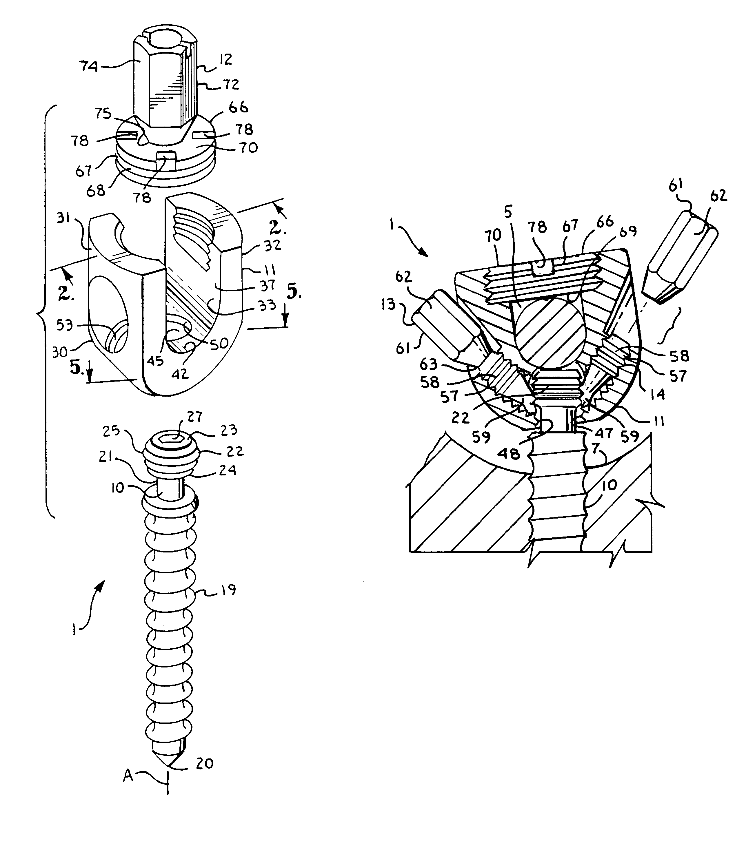
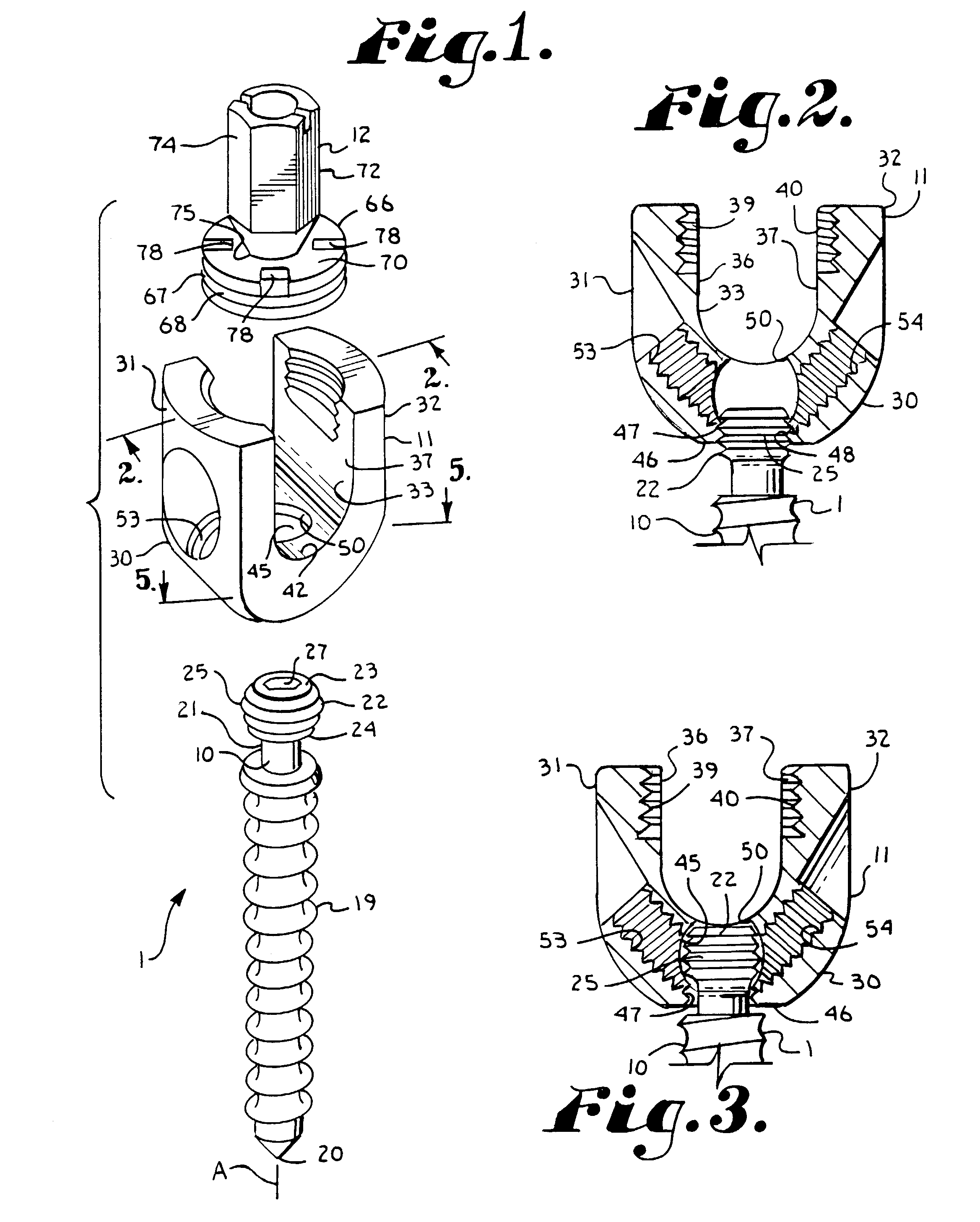
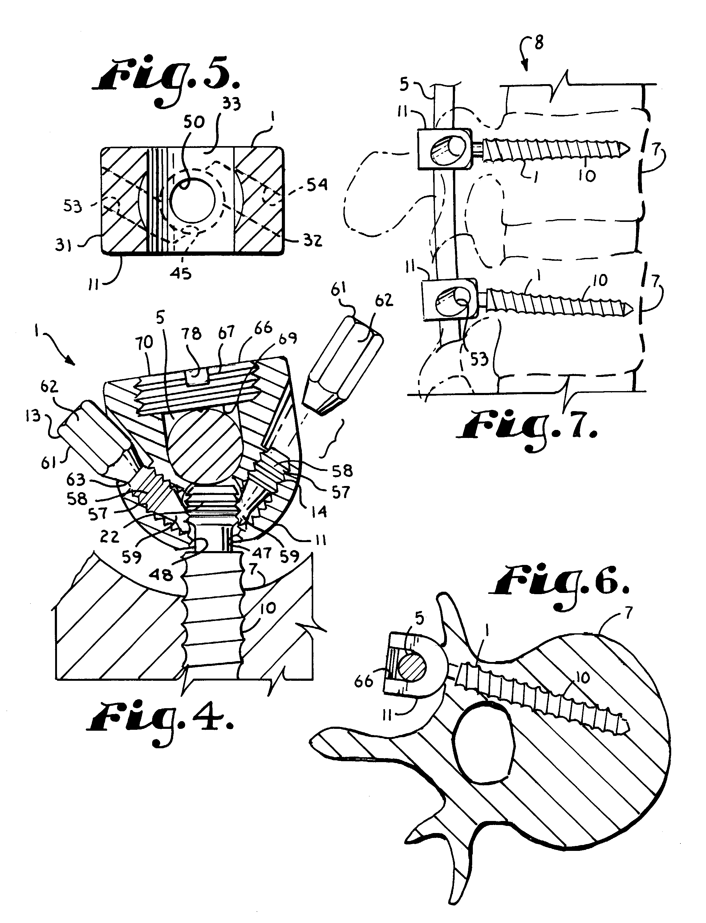
[0023]The reference numeral 1 generally indicates a bone screw in accordance with the present invention. The bone screw 1 captures a rod 5 and is implanted in a vertebra 7 of a patient's spine 8. The bone screw 1 includes a shank 10, a head 11, a closure 12 for the head and a pair of locking set screws 13 and 14.

[0024]The shank 10 is sized and shaped to be screwed into one of the vertebra 7. The shank 10 includes an external thread 19 that extends from an out...


PUM


Abstract

A bone screw having a head and a shank. The shank having a ball thereon and the head having a socket for receiving the ball. The ball being externally threaded and the chamber communicating with the exterior of the head through a threaded bore. The ball being threadably received through the bore and being swivelable in the chamber after passing through the bore. The bone screw including at least one set screw that operably engages the ball to lock the head in position relative to the shank.

Description

BACKGROUND OF THE INVENTION[0001]The present invention is directed to a bone screw of the type wherein a head of the bone screw is swingable or can swivel about the shank of the bone screw until the surgeon is satisfied with the relative placement of the two parts and thereafter the head can be locked in position relative to the shank.[0002]Bone screws are utilized in many types of spinal surgery in order to secure various implants to vertebrae along the spinal column. Bone screws of this type typically have a shank that is threaded and adapted to be implanted into a vertebral body of a vertebrae. The bone screw also includes a head which is designed to extend beyond the vertebrae and which has a channel to receive another implant. Typically the channel will receive a rod or a rod-like member. In bone screws of this type, the head may be open, in which case a closure must be used to close between opposite sides of the head once a rod-like implant is placed therein, or closed wherein...

Claims


Application Information

Patent Timeline
Patent Type & Authority Patents(United States)
IPC IPC(8): A61B17/70A61B19/00
CPCA61B17/7035A61B17/7032A61B2019/307A61B2090/037
Inventor JACKSON, ROGER P.
Owner JACKSON
Why Eureka
Try Eureka