Push-button switch

a push-button switch and push-button technology, applied in the field of push-button switches, can solve the problems of assembly time and significant costs

Active Publication Date: 2005-11-15
ILLINOIS TOOL WORKS INC
View PDF7 Cites 38 Cited by
  • Summary
  • Abstract
  • Description
  • Claims
  • Application Information

AI Technical Summary

Benefits of technology

[0008]The present invention is directed to a push-button switch having a universal assembly including a single body design, a single plunger design, and a single base design to provide various switch options in an overall single package design. The push-button switch may be operated by a mechanical system or a hall-effect system, and also provide a momentary switch

Problems solved by technology

Because of the various switch designs and applications, multiple parts and

Method used


Image

  • Push-button switch
  • Push-button switch
  • Push-button switch

Examples


Embodiment Construction

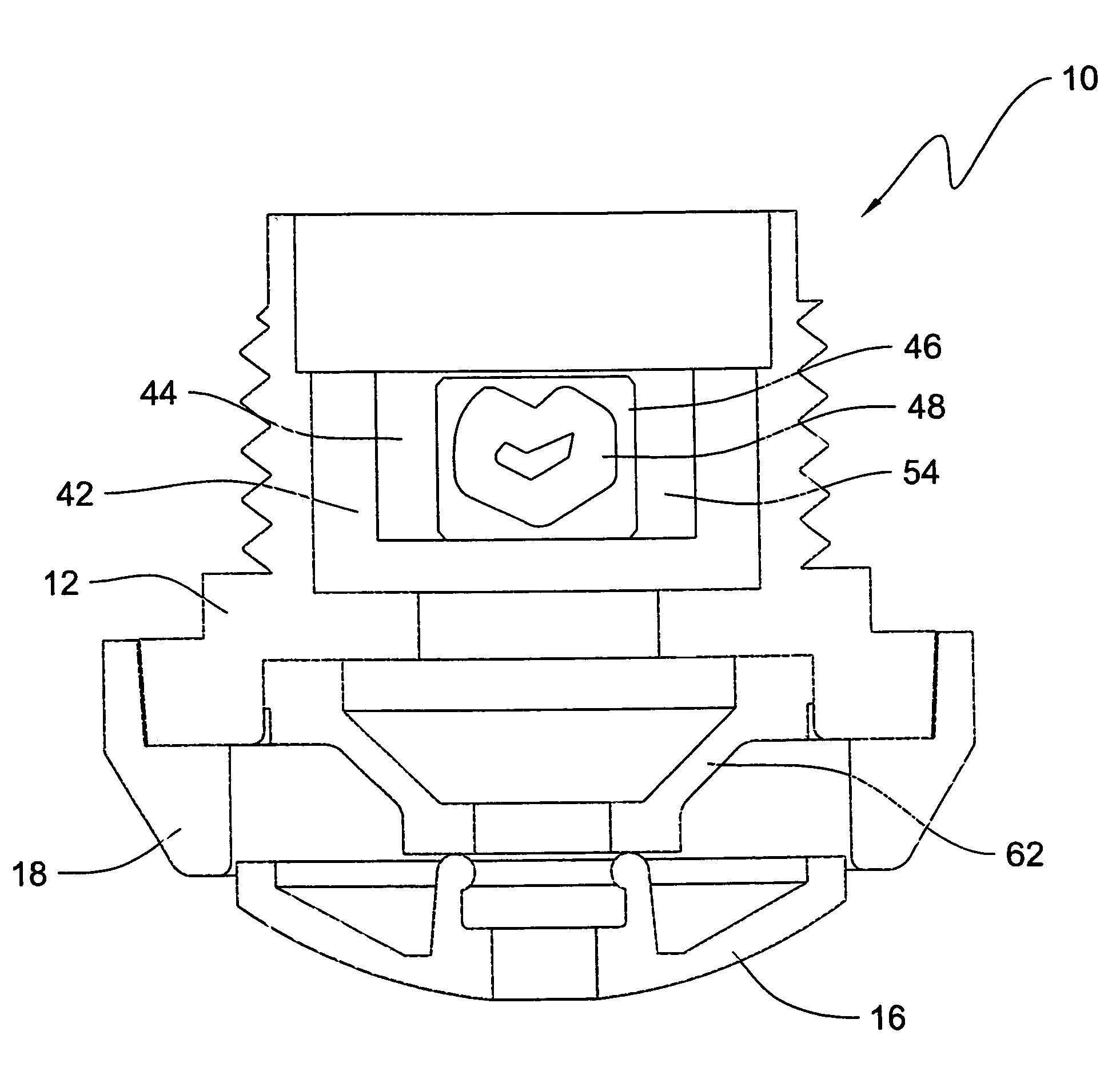
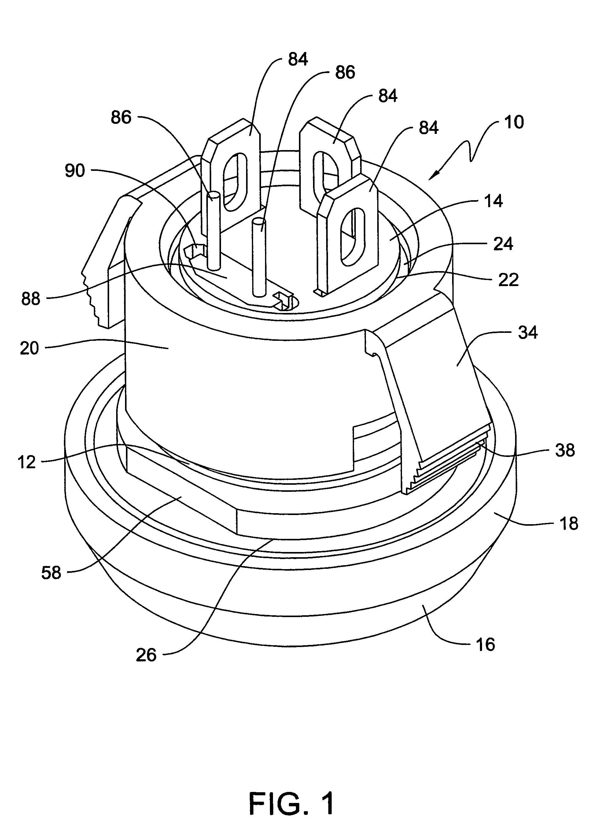
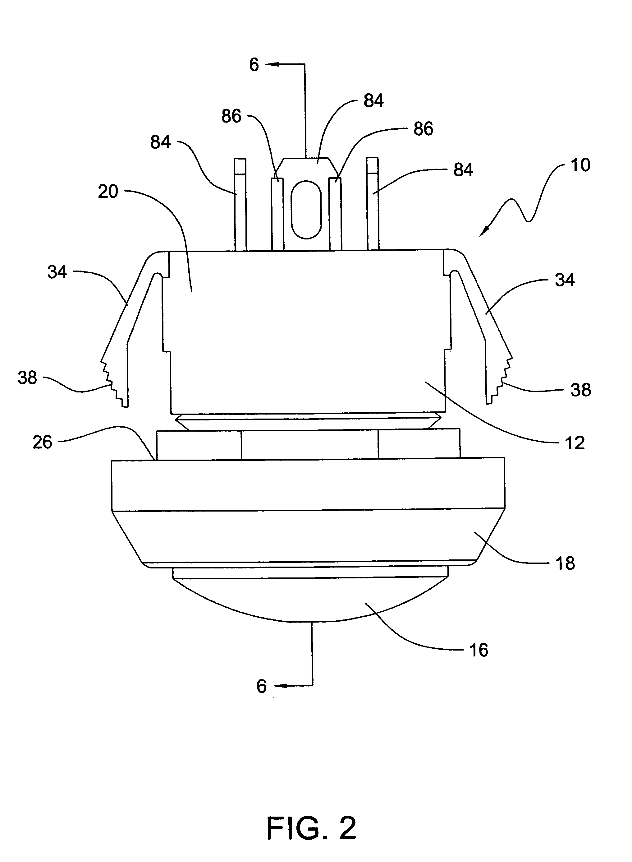
[0024]Referring to the figures there is depicted a push-button switch 10 of the present invention. The push-button switch 10 may be used with numerous applications, such as equipment control handles, outdoor controls, medical equipment, and the like. The push-button switch 10 may be operated by a mechanical system or a hall-effect system, as described below, and provide a momentary switch connection, such as a single push system, or a maintained switch connection, such as a push-push system, also as described below. In addition, the push-button switch 10 may include an LED and accompanying components, along with tactile feedback features and other switch options. With the present invention, a single push-button switch 10 can therefore accommodate all of the foregoing parts and components to provide numerous desirable switch features and options, thereby making the push-button switch 10 applicable for numerous desired applications. One skilled in the art will understand and appreciat...


PUM


Abstract

A push-button switch includes a universal assembly comprising a single body design, a single plunger design, and a single base design to provide various switch options in an overall single package design. The push-button switch of the invention may be operated by either a mechanical switch assembly or a hall-effect system. The push-button switch may also provide a momentary switch connection, such as a single push system, or a maintained switch connection, such as a push-push system. Further, the push-button switch may include feedback mechanisms, such as LED components and the like that provide a visible feedback of the switch connection, and tactile feedback components that also indicate the switch connection.

Description

FIELD OF THE INVENTION[0001]The present invention relates generally to switches and, more particularly, to push-button switches that can be used with various controls, equipment, and other applications.BACKGROUND OF THE INVENTION[0002]Push-button switches are known. Push-button switches are used in various applications such as industrial equipment control handles, outdoor controls, and medical equipment, to name a few. Typically, push-button switches are used to either close or open an electrical circuit depending on the application. For example, with one known type of push-button switch, when the button is pressed, the circuit will close and will stay closed while the button is pressed. Upon the release of the button, the circuit will open. To close the circuit again, the button will need to be re-pressed. These types of switches provide a momentary on / off operation as the button is pressed and released.[0003]A known version of the momentary push-button switch uses a mechanical swi...

Claims


Application Information

Patent Timeline
IPC IPC(8): H01H9/00H01H11/00H01H13/02H01H13/50H01H13/56H03K17/97
CPCH01H11/0006H01H13/50H03K17/97H01H13/02H01H13/564
Inventor ORRICO, MARIO M.PEDERSEN, MICHAEL S.TRUESDALE, BRIAN J.
Owner ILLINOIS TOOL WORKS INC
Why Eureka
Try Eureka