Terminal multiplexer structure

Inactive Publication Date: 2005-11-15
AVERY GRP LTD
View PDF17 Cites 0 Cited by
  • Summary
  • Abstract
  • Description
  • Claims
  • Application Information

AI Technical Summary

Benefits of technology

[0011]Accordingly, line protection can be effected without the requirement for a separa

Problems solved by technology

Such architectures have the disadvantage that failure of one of the DWDM channels will effectively cut out one of the line connection

Method used


Image

  • Terminal multiplexer structure
  • Terminal multiplexer structure
  • Terminal multiplexer structure

Examples


Embodiment Construction

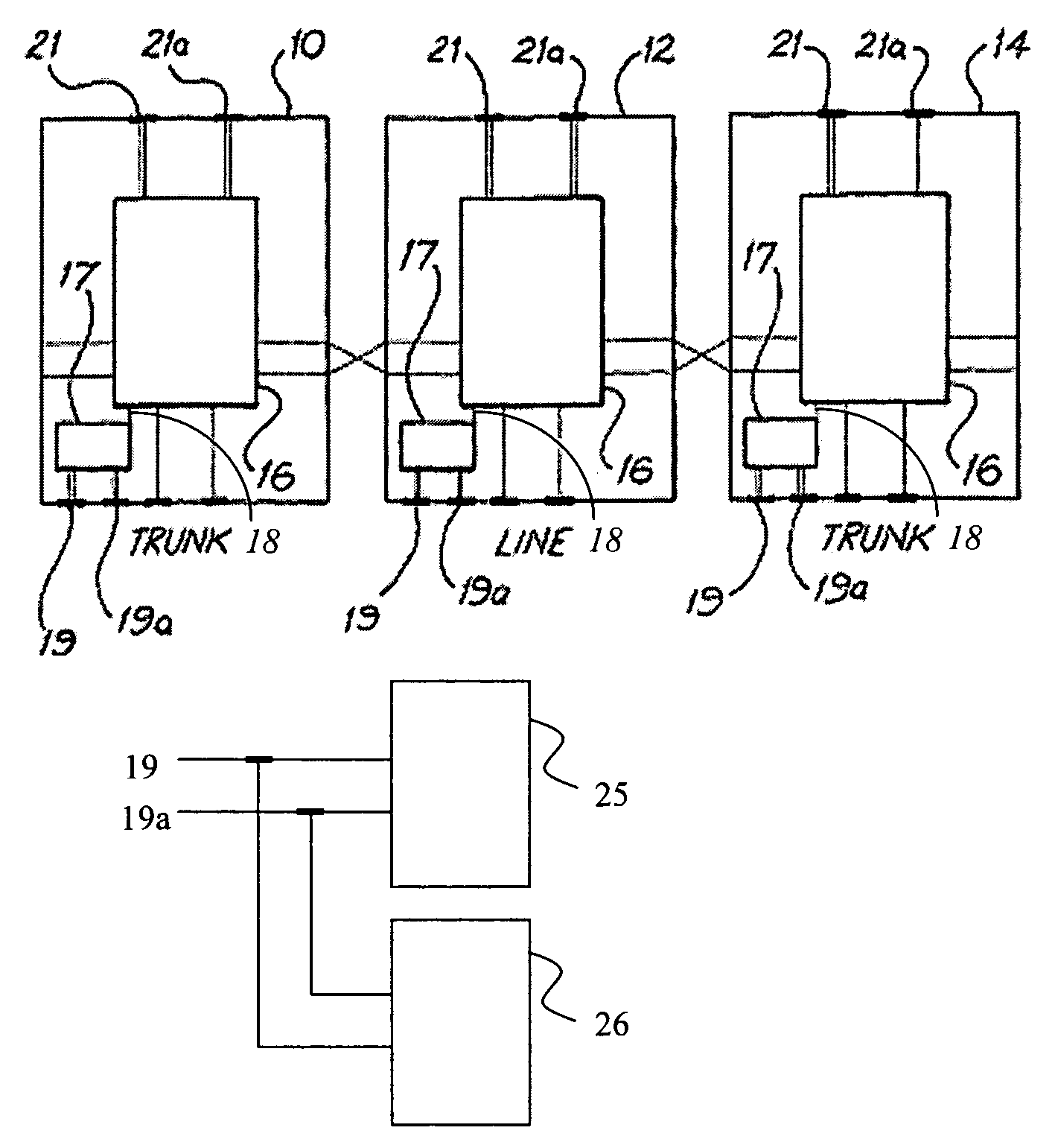
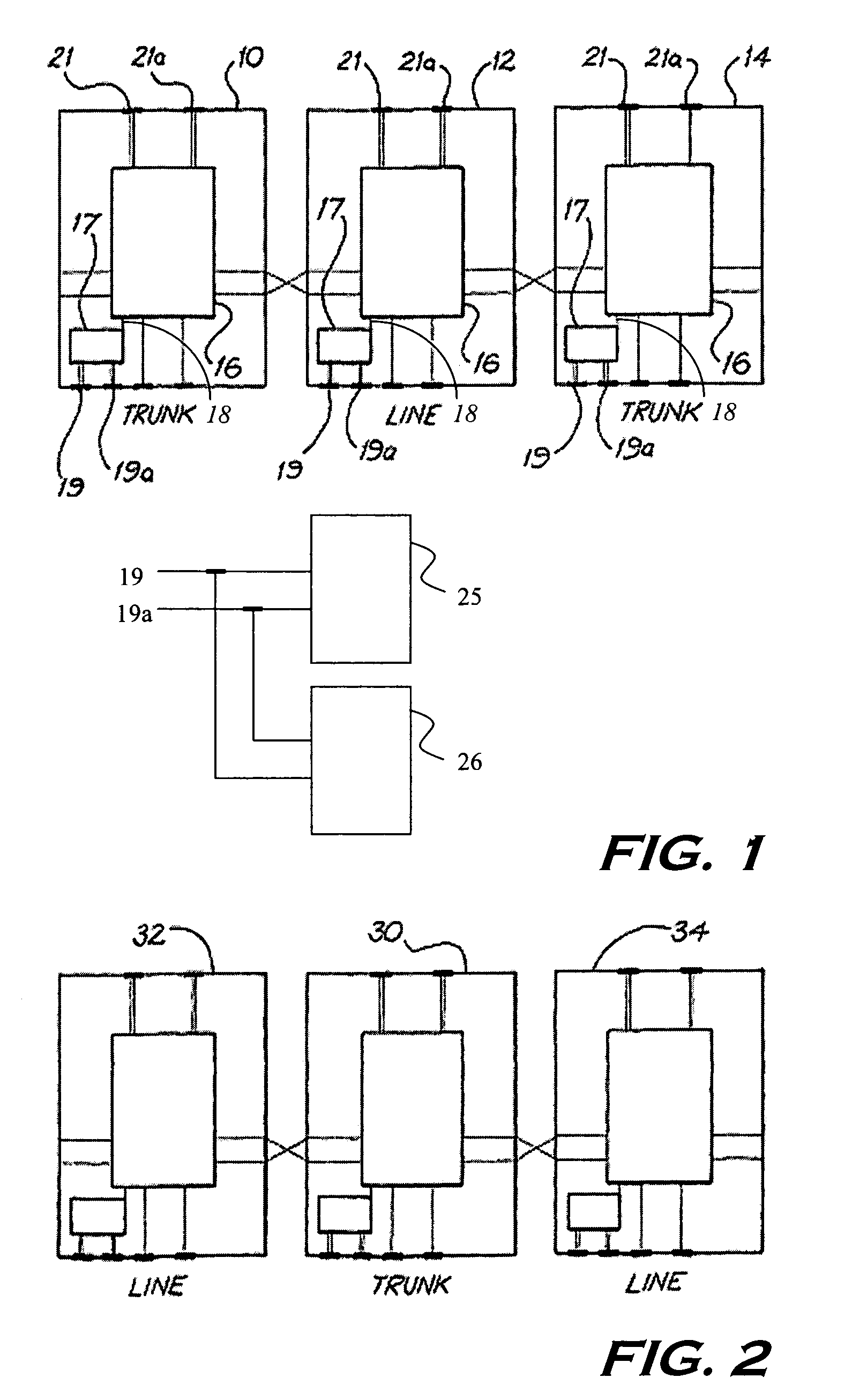
[0024]In FIG. 1, a line interface card 12 is located between two trunk interface cards 10, 14.

[0025]Each of the cards 10, 12, 14 comprises an on-card electronic cross connect switch 16. The cross connect switches 16 are configured in a manner such that the respective interface cards can be selectively connected to either one of its neighbouring interface cards.

[0026]More particularly, in FIG. 1 the centre line interface card 12 can be selectively connected either to the trunk interface card 10 or to the trunk interface card 14, by way of the cross connect switch 16 located on the line interface card 12.

[0027]Each cross connect switch 16 is controlled by an on-board controller 17 of the line or trunk interface cards 10, 12, 14, via an internal control channel 18. The controller 17 is itself controlled via signals received on serial connection ports 19, 19a, from two redundant communication controller (cards) 25 and 26 for default tolerance.

[0028]In use, the on-card cross connect swit...


PUM


Abstract

A terminal multiplexer structure comprising a plurality of line interface cards and a plurality of trunk interface cards wherein each of the line interface cards is connected to at least two of the trunk interface cards and comprises a switch for switching the connection transmission from the line interface board between the two trunk interface cards.

Description

FIELD OF THE INVENTION[0001]The present invention relates to a terminal multiplexer structure for use in a network node system.BACKGROUND OF THE INVENTION[0002]There is a need for providing a flexible dense wavelength division multiplexing (DWDM) and switching architecture, eg for use in network node systems.[0003]Traditional architectures centre around a fixed link between line interfaces and trunk interfaces to channels of the DWDM. Such architectures have the disadvantage that failure of one of the DWDM channels will effectively cut out one of the line connections, ie service to a particular subscriber is disrupted until the faulty DWDM channel has been “repaired”, eg by replacing a DWDM laser.[0004]The present invention seeks to provide a multiplexer structure which addresses this problem.SUMMARY OF THE INVENTION[0005]In accordance with a first aspect of the present invention there is provided a terminal multiplexer structure comprising a plurality of line interface cards and a ...

Claims


Application Information

Patent Timeline
IPC IPC(8): H04Q1/10H04Q1/02H04M3/12H04M3/08H04J14/02H04M3/00H04M7/00
CPCH04J14/0291H04M3/12H04Q1/10H04J14/0212H04J14/0297H04M3/005H04M7/0096
Inventor HALGREN, ROSSCOX, MALCOLM
Owner AVERY GRP LTD
Why Eureka
Try Eureka