Plug and expel flow control device

a flow control device and plug-and-expel technology, applied in the field of plug-and-expel flow control devices, can solve the problems of ineffective production, inconvenient maintenance, and high cost of repair, and achieve the effect of avoiding the problem of inconvenient maintenance, and improving the reliability of the current temporary plug flow control devi

Active Publication Date: 2005-11-22
BAKER HUGHES OILFIELD OPERATIONS LLC
View PDF18 Cites 59 Cited by
  • Summary
  • Abstract
  • Description
  • Claims
  • Application Information

AI Technical Summary

Benefits of technology

[0011]In an exemplary embodiment, the flow control device includes a housing that defines a flowbore therethrough with a restricted diameter portion. The restricted diameter portion presents a seating surface for a plug member and is provided by an annular shell that is shaped to project convexly inwardly. The shell may be fashioned of metal, elastomer or another suitable material, and it is capable of yielding to permit pass...

Problems solved by technology

Leaks in the production tubing string result in inefficient production and can be costly to repair after production has begun.
Unfortunately, current temporary plug flow control devices are problematic or less than reliable in practice.
This type of device is also known commercially as a “well test membrane.” This arrangement is unsatisfactory for some purposes since it does not allow passage of fluid or tools through the tubing string while the tubing string is being tripped into the wellbore.
Upon the application of a predetermined amount of pressure within the tubing string above the plugging ball, several shear screws are sheared, permitting a sleeve within the tubing string to slide downwardly within the flowbore so tha...

Method used


Image

  • Plug and expel flow control device
  • Plug and expel flow control device
  • Plug and expel flow control device

Examples


Embodiment Construction

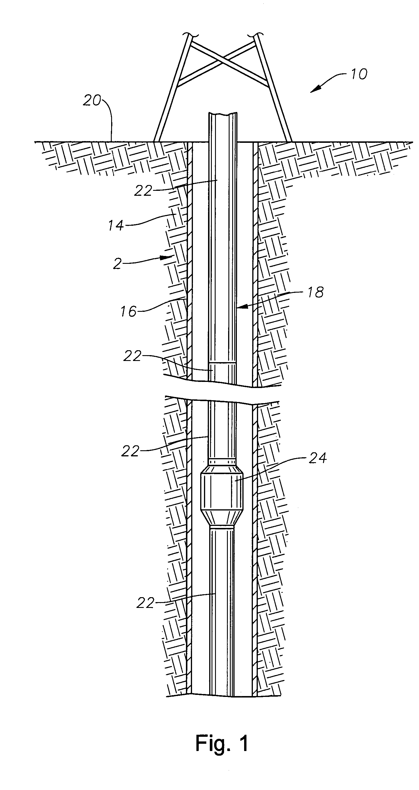
[0018]FIG. 1 schematically illustrates an exemplary production well 10 having a wellbore 12 disposed through the earth 14 to a formation (not shown). The wellbore 12 is cased by casing 16. A production tubing string 18 is disposed within the wellbore 12 from the surface 20 of the well 10, in preparation for the production of hydrocarbons from the formation.

[0019]The production tubing string 18 is made up of a series of individual tubing sections 22, which are affixed to one another by threading, as is known in the art. The tubing string 18 also includes a plug and expel device 24 that is constructed in accordance with the present invention.

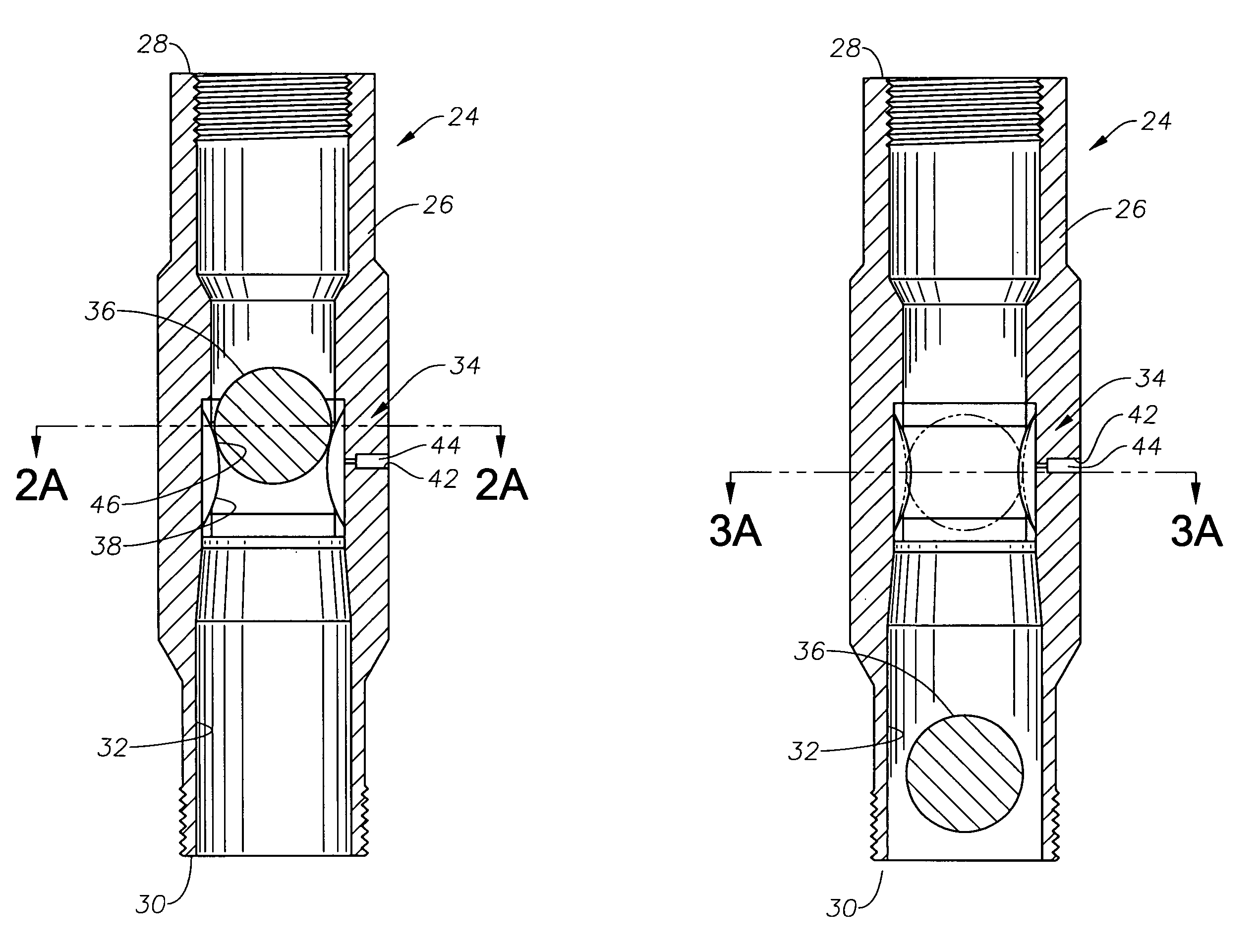
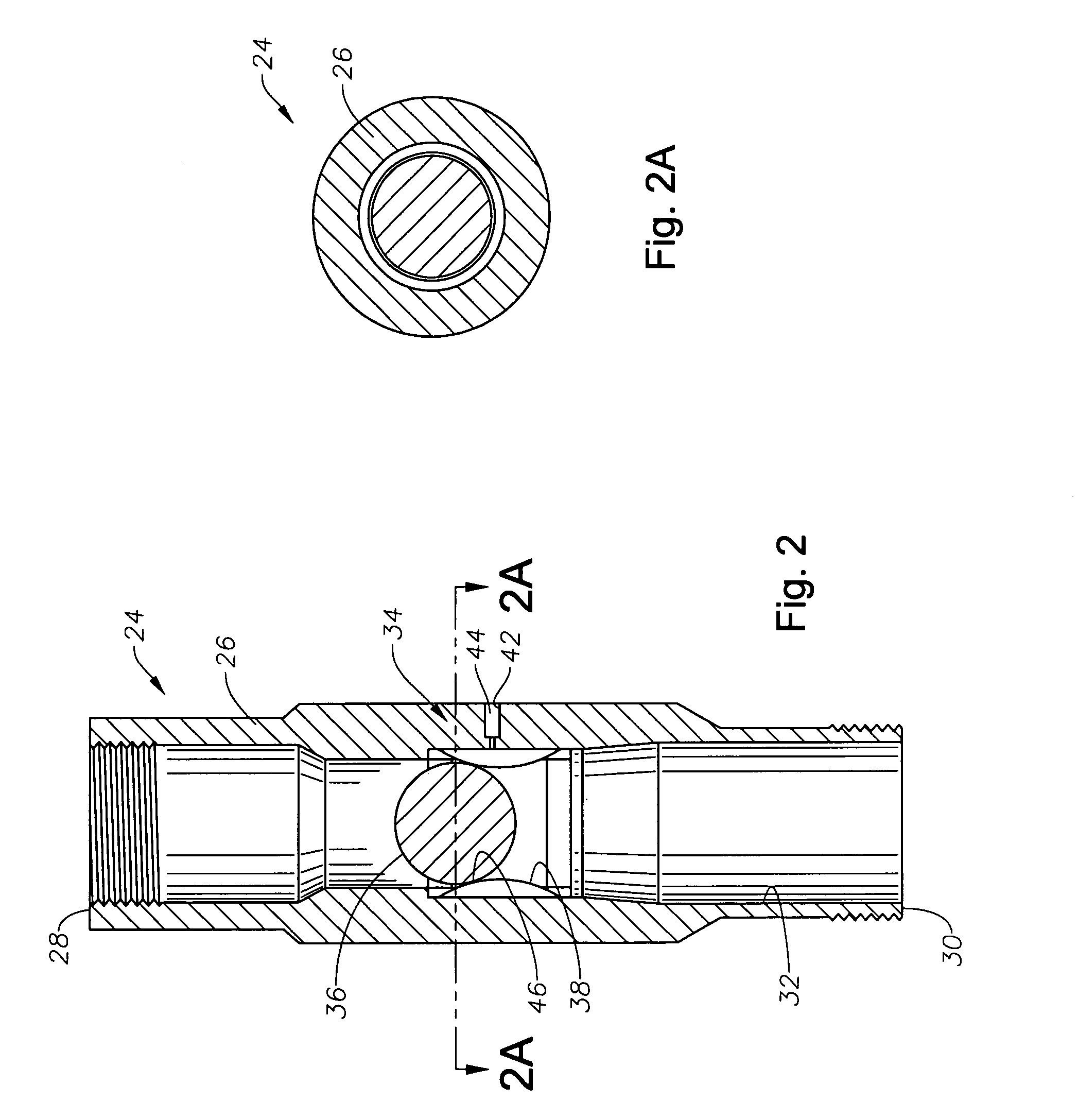
[0020]The structure and operation of the plug and expel device 24 is better appreciated with reference to FIGS. 2, 2A, 3 and 3A. As shown there, the plug and expel device 24 includes a tubular outer sub, or housing, 26 having upper and lower axial ends 28, 30. The ends 28, 30 of the sub 26 are threaded to allow the sub 26 to be incorporated into t...


PUM


Abstract

Devices and methods for fluid flow control within a production tubing string wherein a temporary flow blockage is established and selectively removed from the tubing string so that pressure testing or operation of a hydraulic tool within the string may be performed. A flow control device includes a housing that defines a flowbore therethrough with a restricted diameter portion. The restricted diameter portion presents a seating surface for a plug member and is provided by an annular shell that is shaped to project convexly inwardly. The shell may be fashioned of metal, elastomer or another suitable material, and it is capable of yielding to permit passage of a plug member upon application of a suitably great amount of fluid pressure. In operation, a plugging member is dropped in to the tubing string from the surface of the well and seats upon the seating surface. The tubing string is then pressured up to a first fluid pressure level for testing, tool operation, or the like, and the pressuring up will urge the plugging member against the plug seat in order to effect a fluid seal. When it is desired to remove the plugging member from the tubing string, and reestablish fluid flow through the tubing string, fluid pressure above the plugging member is raised to a second, overpressure level. The plug is then urged through the restricted diameter portion and expelled from the device to the wellbore sump below.

Description

BACKGROUND OF THE INVENTION[0001]1. Field of the Invention[0002]The invention relates generally to flow control devices for establishing temporary obstructions within a tubing string. In certain aspects, the invention also relates to devices and methods for pressure testing of production tubing within a hydrocarbon production well or for operating hydraulic tools within a tubing string.[0003]2. Description of the Related Art[0004]After a production well is drilled, cased, and, if required perforated, a string of production tubing is run into the cased wellbore. Hydrocarbons from a downhole formation are then drawn into the production tubing, under impetus of a surface-based pump, and brought to the surface of the well. After the production tubing is run into the wellbore, it is desirable to test the pressure integrity of the tubing before drawing production fluid from the formation. Leaks in the production tubing string result in inefficient production and can be costly to repair af...

Claims


Application Information

Patent Timeline
IPC IPC(8): E21B47/10
CPCE21B47/1025E21B47/117E21B33/12
Inventor FARQUHAR, GRAHAM E.
Owner BAKER HUGHES OILFIELD OPERATIONS LLC
Why Eureka
Try Eureka